Lower die grinding machine for bracket punching die

A technology for grinding machines and molds, which is applied in the direction of grinding workpiece supports, grinding machine parts, grinding machines, etc. It can solve the problems of reducing grinding efficiency and achieve the effects of improving grinding efficiency, preventing physical fatigue, and reducing friction area

Active Publication Date: 2019-04-09
台州旭龙业五金制品有限公司
View PDF11 Cites 10 Cited by
  • Summary
  • Abstract
  • Description
  • Claims
  • Application Information

AI Technical Summary

Problems solved by technology

[0003] In order to overcome the shortcoming that workers use a hand-held grinding stone to polish the mold for a long time, it is easy to make the body tired, and because the grinding stone and the grinding contact area of ​​the mold are too large, it is eas

Method used


Image

  • Lower die grinding machine for bracket punching die
  • Lower die grinding machine for bracket punching die
  • Lower die grinding machine for bracket punching die

Examples


Embodiment 1

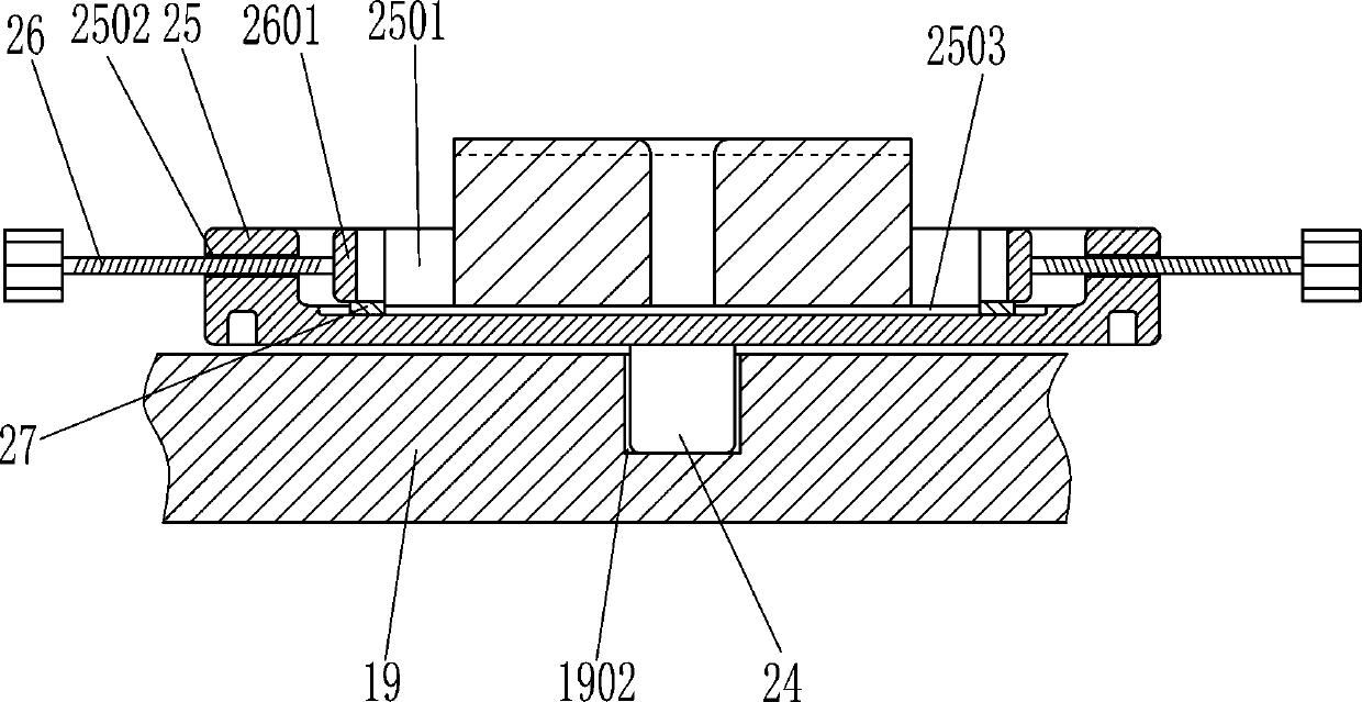
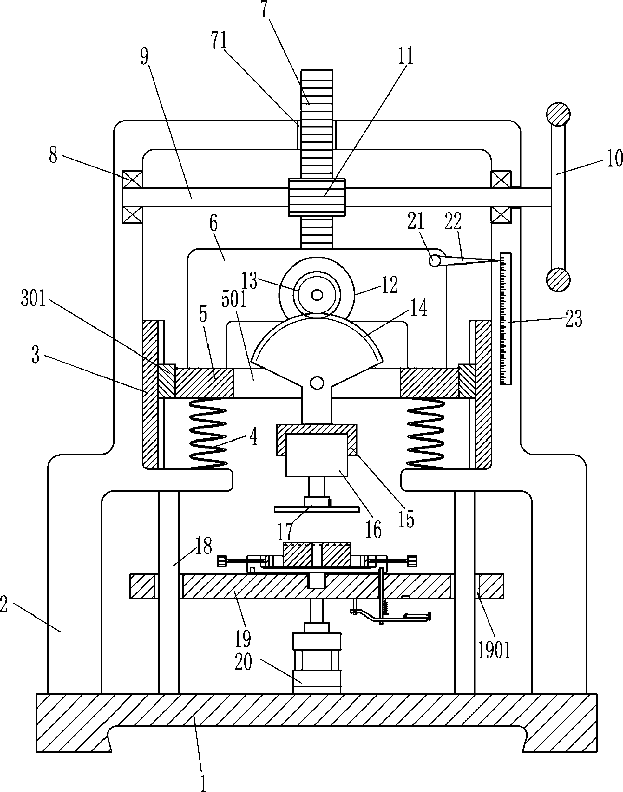
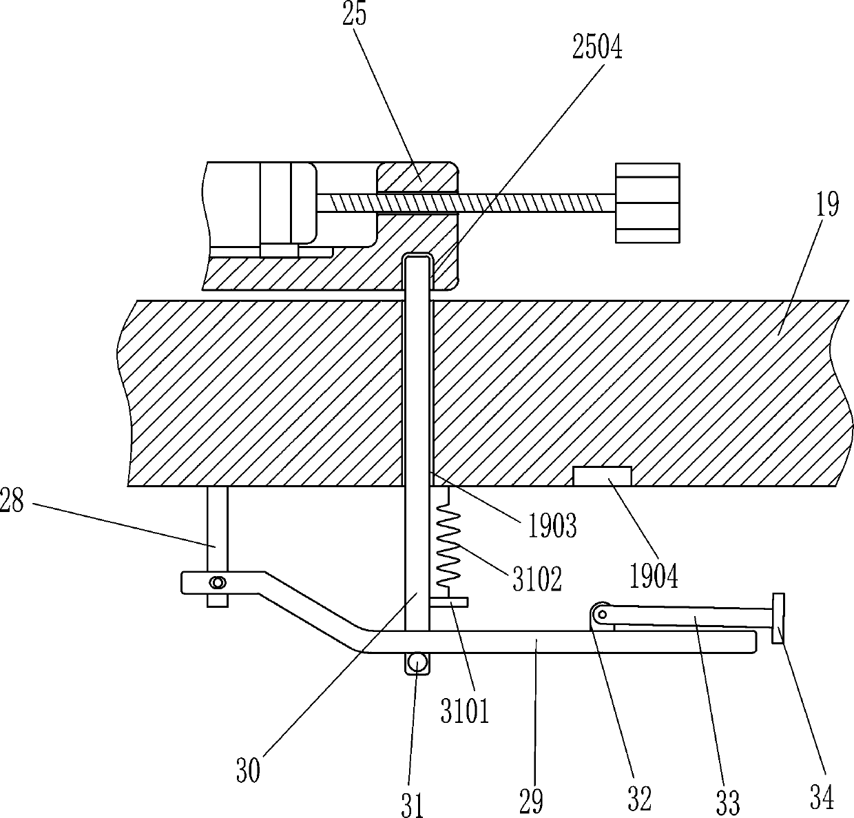
[0021] A kind of mold grinding machine under the bracket punching mold, such as Figure 1-3As shown, it includes a base 1, a frame 2, a slide rail 3, a first slider 301, a first spring 4, a horizontal bracket 5, a U-shaped plate 6, a rack 7, a bearing 8, a shaft 9, and a turntable 10 , the first gear 11, the servo motor 12, the second gear 13, the sector gear 14, the mounting seat 15, the rotating motor 16, the grinding disc 17, the slide bar 18, the chassis 19 and the cylinder 20, and the frame 2 is fixed on the supporting base On the top of the seat 1, two slide rails 3 are provided, which are installed on the upper parts of the left and right walls in the frame 2 respectively. Connected with a horizontal bracket 5, the first spring 4 is provided with two, respectively installed on the left and right sides of the horizontal bracket 5 and the frame 2, the middle part of the horizontal bracket 5 has an opening 501, and the U-shaped plate 6 is installed on the side of the horiz...

Embodiment 2

[0023] A kind of mold grinding machine under the bracket punching mold, such as Figure 1-3 As shown, it includes a base 1, a frame 2, a slide rail 3, a first slider 301, a first spring 4, a horizontal bracket 5, a U-shaped plate 6, a rack 7, a bearing 8, a shaft 9, and a turntable 10 , the first gear 11, the servo motor 12, the second gear 13, the sector gear 14, the mounting seat 15, the rotating motor 16, the grinding disc 17, the slide bar 18, the chassis 19 and the cylinder 20, and the frame 2 is fixed on the supporting base On the top of the seat 1, two slide rails 3 are provided, which are installed on the upper parts of the left and right walls in the frame 2 respectively. Connected with a horizontal bracket 5, the first spring 4 is provided with two, respectively installed on the left and right sides of the horizontal bracket 5 and the frame 2, the middle part of the horizontal bracket 5 has an opening 501, and the U-shaped plate 6 is installed on the side of the hori...

Embodiment 3

[0026] A kind of mold grinding machine under the bracket punching mold, such as Figure 1-3 As shown, it includes a base 1, a frame 2, a slide rail 3, a first slider 301, a first spring 4, a horizontal bracket 5, a U-shaped plate 6, a rack 7, a bearing 8, a shaft 9, and a turntable 10 , the first gear 11, the servo motor 12, the second gear 13, the sector gear 14, the mounting seat 15, the rotating motor 16, the grinding disc 17, the slide bar 18, the chassis 19 and the cylinder 20, and the frame 2 is fixed on the supporting base On the top of the seat 1, two slide rails 3 are provided, which are installed on the upper parts of the left and right walls in the frame 2 respectively. Connected with a horizontal bracket 5, the first spring 4 is provided with two, respectively installed on the left and right sides of the horizontal bracket 5 and the frame 2, the middle part of the horizontal bracket 5 has an opening 501, and the U-shaped plate 6 is installed on the side of the hori...


PUM


Abstract

The invention relates to a grinding machine, in particular to a lower die grinding machine for a bracket punching die. Therefore, the technical aimof the invention is to provide the lower die grindingmachine for the bracket punching die, wherein the lower die grinding machine for the bracket punching die is capable of preventing physical strain and improving grinding efficiency. According to thetechnical scheme, the lower die grinding machine for the bracket punching die comprises a base, a frame, sliding rails, first sliding blocks, first springs, a transverse bracket, a U-shaped plate, a rack, bearings, a shaft rod, a turntable, a first gear, a servo motor and the like. The frame is fixed on the top of the base which plays a supporting role, the two sliding rails are correspondingly installed on the upper parts of the left wall and the right wall in the frame, and the sliding rails are slidably connected with the first sliding blocks. According to the lower die grinding machine, asector gear drives a mounting seat to swing, so that a grinding disc can be tilted through a rotating motor, the friction area during grinding of the grinding disc and a lower die can be reduced, anda worker is not required to grind the die with a hand-held grinding stone, so that physical strain is prevented, and the grinding efficiency is improved.

Description

technical field [0001] The invention relates to a grinder, in particular to a grinder for the lower die of a bracket punching die. Background technique [0002] After the mold has been used for a period of time, there will be rounded corners on the mold. For this reason, the mold needs to be polished. At present, when the mold is polished, the worker usually uses a hand-held grinding stone to polish the mold. Because the grinding stone is in contact with the mold. The area is too large, so it is easy to reduce the efficiency of grinding, and the body of the grinding workers is easy to be tired for a long time. In order to improve the grinding efficiency, the grinding stone will be installed on the motor to grind the mold manually, and the mold needs to be fixed manually, which will increase Artificial labor intensity. Contents of the invention [0003] In order to overcome the shortcoming that workers use a hand-held grinding stone to polish the mold for a long time, it i...

Claims


Application Information

Patent Timeline
IPC IPC(8): B24B19/20B24B41/06B24B47/12B24B47/20B24B47/22
CPCB24B19/20B24B41/06B24B47/12B24B47/20B24B47/22
Inventor 肖勇斌
Owner 台州旭龙业五金制品有限公司
Why Eureka
Try Eureka