
Lake surface cleaning machine

A sweeper and water inlet technology, which is used in the cleaning of open water surfaces, water conservancy projects, construction, etc., can solve the problems of water surface cleaning that cannot be eutrophicated, and the device cannot work, and achieves good practical application value, transportation and maintenance. Convenience and operability

Active Publication Date: 2019-04-09
HOHAI UNIV
View PDF7 Cites 1 Cited by
  • Summary
  • Abstract
  • Description
  • Claims
  • Application Information

AI Technical Summary

Problems solved by technology

However, because the hanger, long frame, hydraulic cylinder, throwing handle, etc. are hinged with each other, and the oars are also hinged with the hull, and they are all exposed to the outside and in direct contact with the lake surface. Work
Therefore, the device cannot clean the eutrophic water surface

Method used


Image

  • Lake surface cleaning machine
  • Lake surface cleaning machine
  • Lake surface cleaning machine

Examples


Embodiment 1

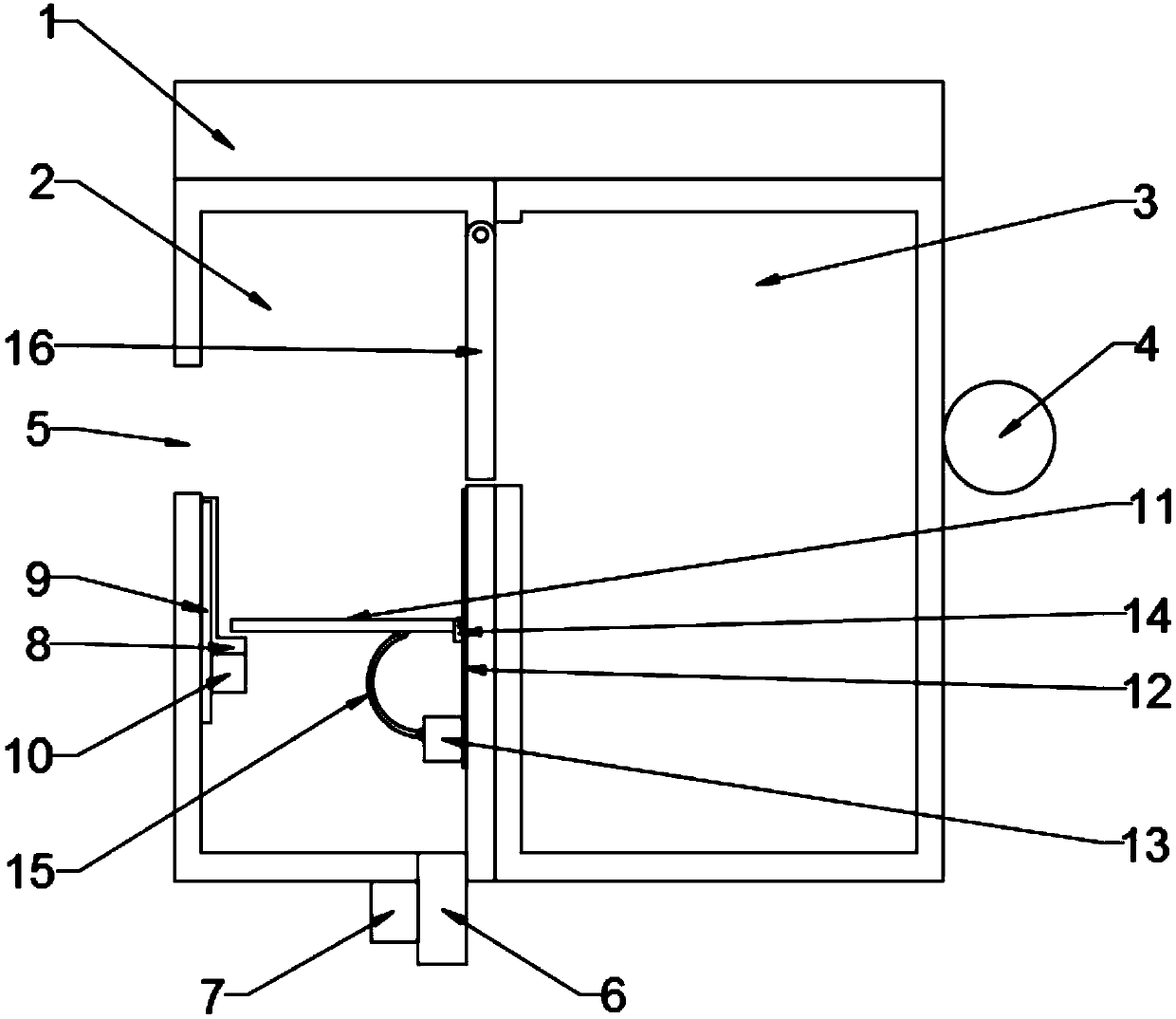
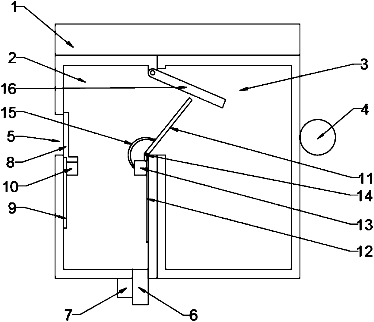
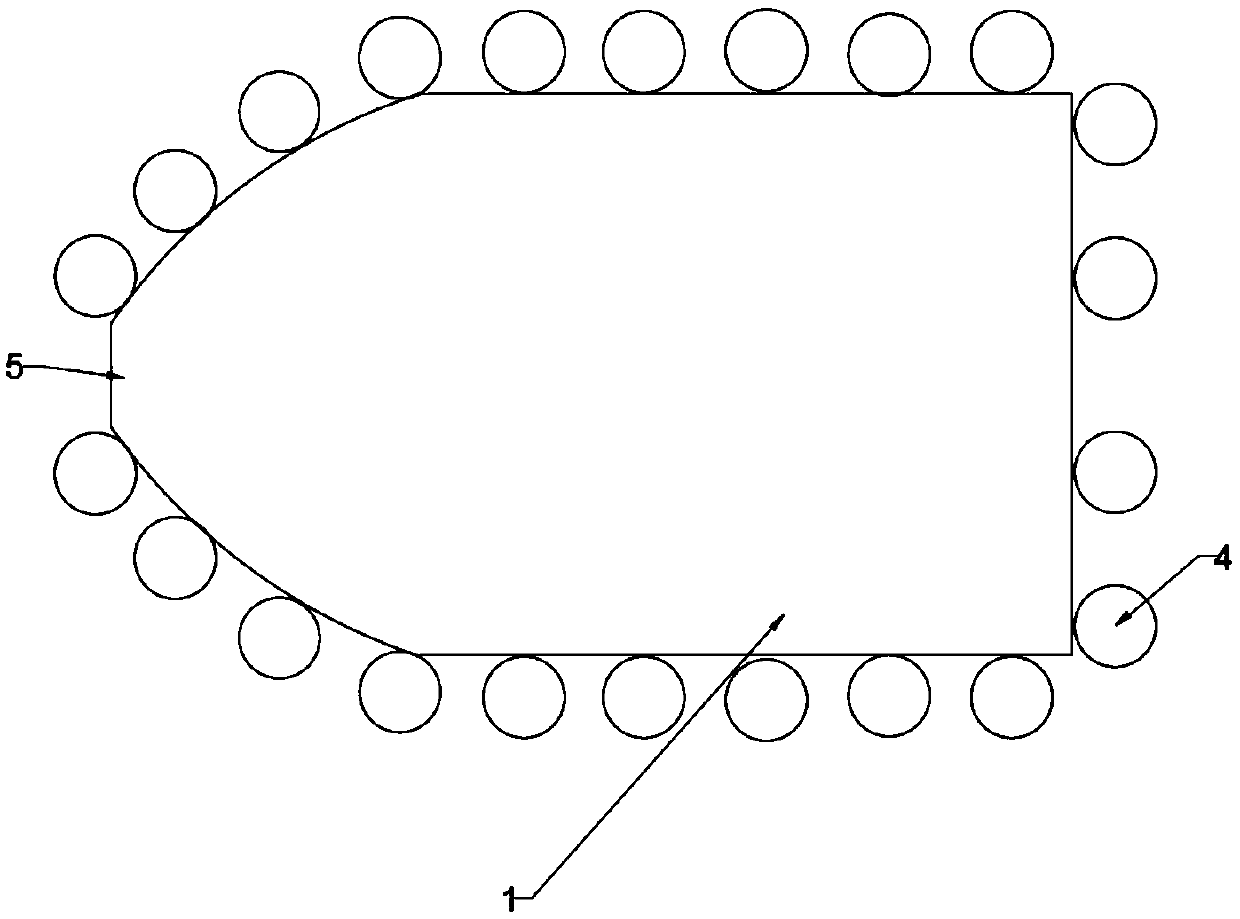
[0034] Such as Figure 1~3 As shown, the lake cleaning machine provided in this embodiment includes a solar panel 1, a water inlet bin 2, and a storage bin 3. The water inlet bin 2 and the storage bin 3 are located under the solar panel 1 side by side. A circle of air bags 4 are arranged around the water bin 2 and the storage bin 3;

[0035] The water inlet bin 2 is provided with a water inlet 5, a water outlet 6, a water pump 7, a baffle 8, a first slide rail 9, a first motor 10, a trash rack 11, a second slide rail 12, and a second motor 13; The first slide rail 9 is located on both sides of the water inlet 5, the first motor 10 drives the baffle plate 8 to lift up and down on the first slide rail 9, and the bottom end of the baffle plate 8 is bent by 90 ° into shape; the water outlet 6 and the water pump 7 are located below the water inlet chamber 2;

[0036] The second slide rail 12 and the second motor 13 are arranged on the side adjacent to the storage bin 3 in the w...

Embodiment 2

[0042] Such as Figure 4 As shown, the lake cleaning machine provided in this embodiment has been improved as follows on the basis of Embodiment 1:

[0043] 1. A roller 17 is provided at one end of the trash rack 11 resting on the bottom of the baffle plate 8, and a push rod 18 is vertically provided on the side of the trash rack 11 close to the roller 17;

[0044] 2. The water inlet 5 is trumpet-shaped;

[0045] 3. An engine 19 and a propeller 20 are arranged below the water inlet bin 2 and the storage bin 3 .


PUM


Abstract

The invention provides a lake surface cleaning machine. A water inlet bin and a storage bin are located below a solar cell panel side by side, and a circle of air bags are arranged on the periphery ofthe water inlet bin and the periphery of the storage bin. The first sliding rails are located on the two sides of the water inlet, a first motor drives a baffle to ascend and descend on the first sliding rails, and the bottom end of the baffle is bent by 90 degrees to form a shape shown in the specification. A water outlet and a water pump are positioned below the water inlet bin. A second sliding rail and a second motor are arranged on the side, adjacent to the storage bin, in the water inlet bin. One end of a trash rack is horizontally arranged at the bottom end of the baffle in an overlapping manner, and the other end is provided with a universal hinge and located on the second sliding rail. The second motor is connected with the trash rack through an arc-shaped connecting rod, the twoends of the arc-shaped connecting rod can freely rotate, and the second motor drives the trash rack to ascend and descend. An opening is formed between the water inlet bin and the storage bin, a water separation plate used for sealing the opening is further arranged, the water separation plate freely rotates with the top edge of the water separation plate as the axis, and the second sliding railextends to the bottom edge of the water separation plate. The lake surface cleaning machine is high in sweeping efficiency, manpower is saved, and machine parts are prevented from being wound by substances such as algae.

Description

technical field [0001] The invention belongs to the field of water body cleaning, in particular to a lake surface cleaning machine. Background technique [0002] In park artificial lakes, open-air swimming pools and large outdoor lakes, leaves, duckweed, algae, etc. are easy to float on the surface of the lake, which affects the appearance, and if the water body is not cleaned up in time, foul odor and eutrophication may occur. In response to this phenomenon, the current solution is mainly manual salvage on a regular basis, which is time-consuming and labor-intensive. [0003] In the prior art, the patent No. 201710891267.8 is an invention "a traveling type lake surface garbage collection device", which salvages and stores the lake surface garbage through the collection frame and hull, and makes the boat automatically drive to clean up the lake surface garbage by specifying the sliding track of the oars. save human effort. However, the condition of the lake surface is comp...

Claims


Application Information

Patent Timeline
IPC IPC(8): E02B15/10
CPCE02B15/104
Inventor 周悦董增川金大伟叶海焯徐伟任杰
Owner HOHAI UNIV
Learn More