
Ventilator and ventilation system

A ventilator and fan unit technology, applied in the direction of mechanical equipment, machines/engines, liquid fuel engines, etc., can solve the problems of inconvenient transportation and installation, inconvenient maintenance, large volume, etc., and achieve the effect of easy transportation, easy maintenance and maintenance

Pending Publication Date: 2019-04-09
广东爱美信电器有限公司
View PDF0 Cites 1 Cited by
  • Summary
  • Abstract
  • Description
  • Claims
  • Application Information

AI Technical Summary

Problems solved by technology

For the existing ventilator, its volume is large, it is not convenient for transportation and installation, and it is also not convenient for maintenance

Method used


Image

  • Ventilator and ventilation system
  • Ventilator and ventilation system
  • Ventilator and ventilation system

Examples


no. 1 example

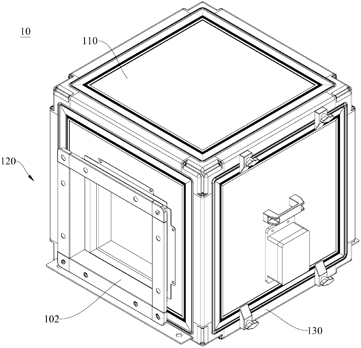
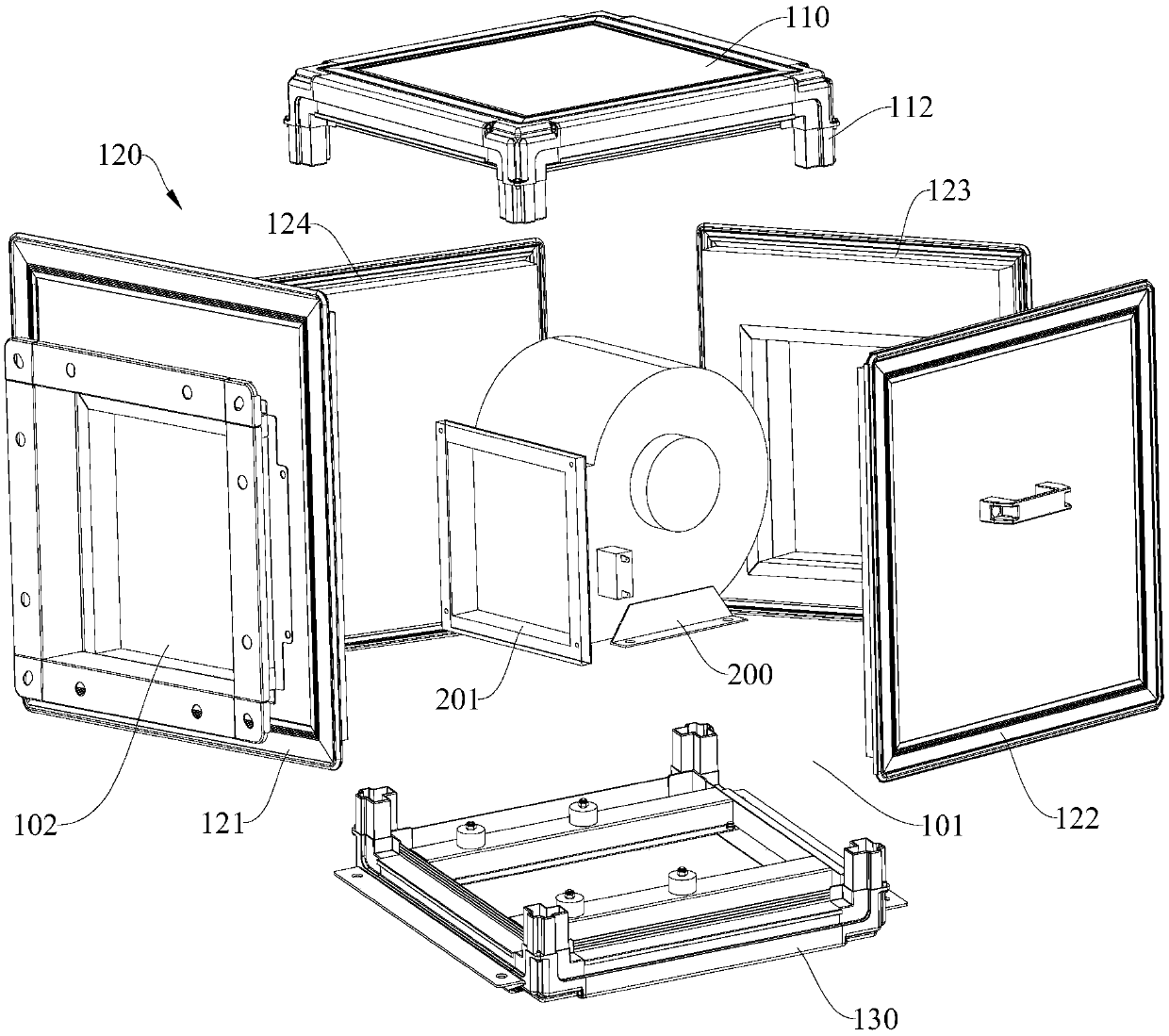
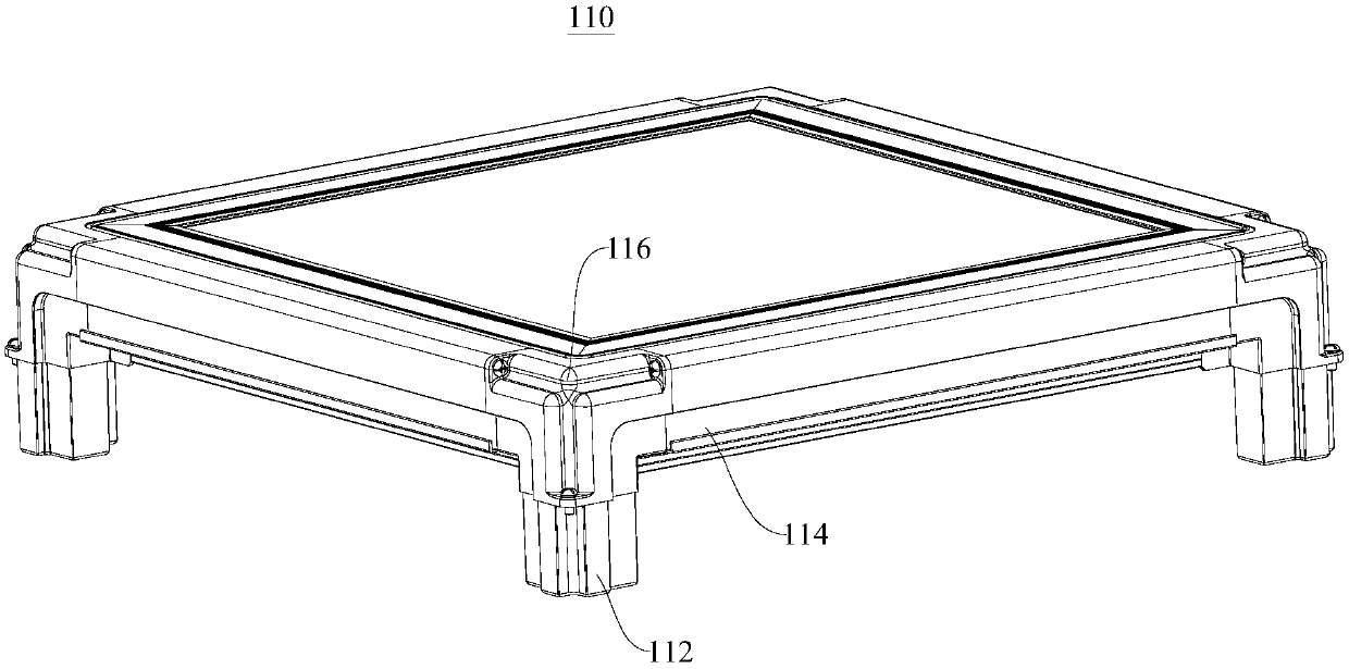
[0033] Please refer to Figure 1 to Figure 4 , the present embodiment provides a ventilator 10, which has the characteristics of simple structure and convenient assembly and disassembly, and can also be easily transported.

[0034] The ventilator 10 provided by this embodiment includes a housing assembly 100 and a fan unit 200. The housing assembly 100 includes a top plate 110, a surrounding plate 120 and a bottom plate 130. The top plate 110 and the bottom plate 130 are located on the opposite sides of the surrounding plate 120 and are connected to the surrounding plate. 120 is detachably connected, the top plate 110, the enclosure 120 and the bottom plate 130 enclose the installation space 101, the enclosure 120 is provided with a vent 102 communicating with the installation space 101, the fan unit 200 is installed on the bottom panel 130, and the fan unit 200 The air outlet 201 communicates with the air outlet 102 and the air is discharged through the air outlet 102 .

[0...

no. 2 example

[0057] Please refer to Figure 1 to Figure 4 , This embodiment provides a ventilation system (not shown in the figure), which has the characteristics of simple structure and convenient disassembly and assembly, and can also be convenient for transportation.

[0058] The ventilation system provided in this embodiment includes a ventilator 10 and a pipeline (not shown). The ventilator 10 includes a housing assembly 100 and a fan unit 200. The housing assembly 100 includes a top plate 110, a surrounding plate 120 and a bottom plate 130. The top plate 110 and the bottom plate 130 are located on opposite sides of the surrounding plate 120 and are detachably connected to the surrounding plate 120. , the top plate 110, the surrounding plate 120 and the bottom plate 130 enclose the installation space 101, the ventilation opening 102 communicating with the installation space 101 is arranged on the surrounding plate 120, the fan unit 200 is installed on the bottom plate 130, and the air...


PUM


Abstract

The invention discloses a ventilator and a ventilation system, and relates to the technical field of ventilation equipment. The ventilator comprises a shell assembly and a ventilator set; the shell assembly comprises a top plate, a surrounding plate and a bottom plate, wherein the top plate and the bottom plate are positioned on two opposite sides of the surrounding plate and are detachably connected with the surrounding plate, and the top plate, the surrounding plate and the bottom plate enclose a mounting space; a ventilation opening communicating with the mounting space is formed in the surrounding plate; and the ventilator set is arranged on the bottom plate, an air outlet of the ventilator set communicates with the ventilation opening, and air is discharged through the ventilation opening. The invention further provides the ventilation system comprising the ventilator. The ventilator and the ventilation system have the characteristics of being simple in structure and convenient todisassemble and assemble, and meanwhile, the ventilator and the ventilation system can be conveniently transported.

Description

technical field [0001] The invention relates to the technical field of ventilating equipment, in particular, to a ventilator and a ventilating system. Background technique [0002] The ventilator is a machine that relies on the input mechanical energy to increase the gas pressure and discharge the gas. It is a driven fluid machine. For the existing ventilator, its volume is relatively large, and it is inconvenient to transport and install, and it is also inconvenient to overhaul. Contents of the invention [0003] The object of the present invention is to provide a ventilator, which has the characteristics of simple structure and convenient assembly and disassembly, and can also be convenient for transportation. [0004] The present invention provides a kind of technical solution about ventilator: [0005] A ventilator, comprising a shell assembly and a fan unit, the shell assembly includes a top plate, a surrounding plate and a bottom plate, the top plate and the bottom...

Claims


Application Information

Patent Timeline
IPC IPC(8): F04D25/08F04D29/00
CPCF04D25/08F04D29/002
Inventor 林超辉朱建荣唐文锋
Owner 广东爱美信电器有限公司
Learn More