High-overload-impact-resistant synchronous four-channel folding wing locking and unfolding mechanism and operation method thereof

A technology of unfolding mechanism and folding wings, which is applied in the direction of projectiles, offensive equipment, weapon types, etc. It can solve the problems of complex structure, inability to lock the impact force, and large impact when the wing surface is unfolded in place, so as to improve consistency and reliability performance, improve safety and reliability, and require high synchronization

Active Publication Date: 2019-04-09
XIAN MICROELECTRONICS TECH INST
View PDF5 Cites 10 Cited by
  • Summary
  • Abstract
  • Description
  • Claims
  • Application Information

AI Technical Summary

Problems solved by technology

At present, the folding wing deployment mechanism of domestic guided munitions mostly adopts the four-way independent push of pyrotechnics, that is, the design method of four pyrotechnics being pushed separately, and the mechanism locks and releases. This method has complex structural design and poor synchronization of four-way wing surface deployment. , when the airfoil is deployed in place, the impact is large, and there is a risk that the airfoil is not securely locked when the airfoil is deployed in place, and the airflow on the airfoil is greatly disturbed, resulting in the risk of instability of the flight attitude of the projectile
[0003] At present, the folding wings mostly adopt the locking strategy of not locking initially or installing an independent locking and releasing device. For the former, there is a risk of mis-deployment during launch. The la...

Method used


Image

  • High-overload-impact-resistant synchronous four-channel folding wing locking and unfolding mechanism and operation method thereof
  • High-overload-impact-resistant synchronous four-channel folding wing locking and unfolding mechanism and operation method thereof
  • High-overload-impact-resistant synchronous four-channel folding wing locking and unfolding mechanism and operation method thereof

Examples


Embodiment Construction

[0037] In describing the present invention, it is to be understood that the terms "center", "upper", "lower", "vertical", "horizontal", "top", "bottom", "inner", "outer", The orientation or positional relationship indicated by "one side", "one end", "one side", etc. is based on the orientation or positional relationship shown in the drawings, and is only for the convenience of describing the present invention and simplifying the description, rather than indicating or implying No device or element must have a specific orientation, be constructed, and operate in a specific orientation and therefore should not be construed as limiting the invention.

[0038] In the description of the present invention, it should be noted that unless otherwise specified and limited, the terms "installation", "connection" and "connection" should be understood in a broad sense, for example, it can be a fixed connection or a detachable connection. Connected, or integrally connected; it may be mechani...


PUM


Abstract

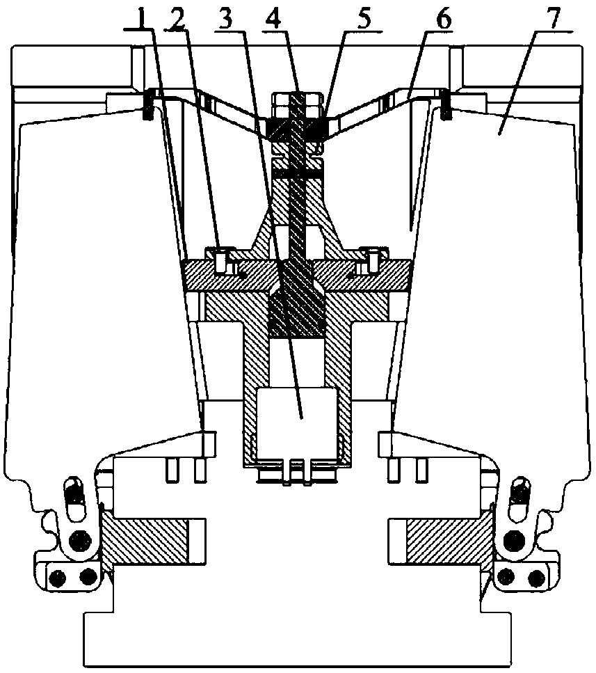
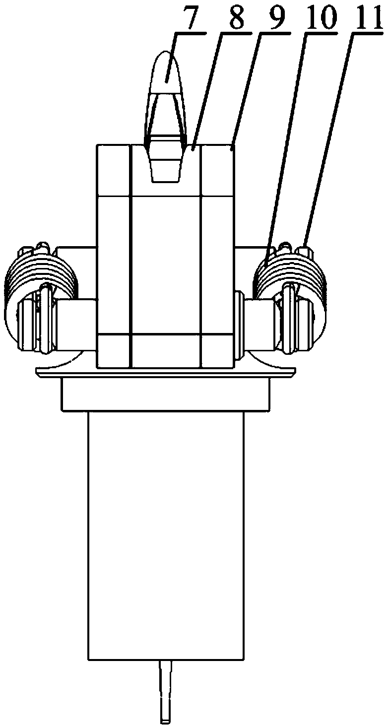
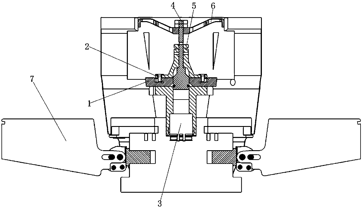
The invention discloses a high-overload-impact-resistant synchronous four-channel folding wing locking and unfolding mechanism and an operation method of the high-overload-impact-resistant synchronousfour-channel folding wing locking and unloading mechanism. The folding wing locking and unfolding mechanism is installed on a rudder and comprises four rudder wings, locking buffering devices and aninitiator thrust cylinder. The four rudder wings are installed on the corresponding locking buffering devices correspondingly and connected with a rudder speed reducer through base output shafts. Theinitiator thrust cylinder is fixed to the center of the rudder, connected with the four rudder wings through locking claws and used for initial folding locking and in-place unfolding of the rudder wings. The high-overload-impact-resistant synchronous four-channel folding wing locking and unfolding mechanism has the features of being simple in structure, good in synchronism, reliable in locking andthe like. The high-overload-impact-resistant synchronous four-channel folding wing locking and unfolding mechanism is suitable for the application field of guided munition folding wings which are large in impact overload, short in unfolding time and high in synchronism requirement.

Description

technical field [0001] The invention belongs to the technical field of guided ammunition folding wings, and in particular relates to a synchronous four-channel folding wing locking and unfolding mechanism and a method thereof which are resistant to high overload impacts. Background technique [0002] The missile wing is an important part of the missile body. In order to make the missile and rocket device miniaturized and facilitate transportation and storage, guided munitions widely adopt the form of folded rudder wings. At present, the folding wing deployment mechanism of domestic guided munitions mostly adopts the four-way independent push of pyrotechnics, that is, the design method of four pyrotechnics being pushed separately, and the mechanism locks and releases. This method has complex structural design and poor synchronization of four-way wing surface deployment. , When the airfoil is deployed in place, the impact is large, and there is a risk that the airfoil is not s...

Claims


Application Information

Patent Timeline
IPC IPC(8): F42B10/02
CPCF42B10/02
Inventor 阎彬龚荣文张波左君龙
Owner XIAN MICROELECTRONICS TECH INST
Why Eureka
Try Eureka