
Patsnap Eureka
For R&D, Patsnap Eureka makes reading and utilizing patents & technical documents easy.
Patsnap Eureka AIR
Designed for self-driven R&D workflows. Generate viable solutions, solve complex R&D challenges, empower your innovation with AI.

Patsnap Eureka Materials
Designed for material experts only. Revolutionize your material R&D, from search, analyze, to developing new materials.

TechResearch
Generate reliable direction feasibility study reports for your R&D in just a few steps.

TechSeek
Discover and master advanced knowledge NOW. Basics, ideas, possibilities, all at once.

TechMind
As an expert in R&D Theories, TechMind can generates customized viable solutions instantly.

TechRisk
Analyze your overall solution with one click, know your potential R&D risks in advance.

TechMonitor
Get weekly tech updates, stay abreast of the latest tech innovations and key insights.
Flange binding machine
A glue-mounting machine and flange glue technology, applied in the direction of supporting insulators, electrical components, insulators, etc., can solve problems such as poor safety protection, poor compatibility, and low operability, and achieve the effect of meeting operational requirements
- Summary
- Abstract
- Description
- Claims
- Application Information
AI Technical Summary
Problems solved by technology
Method used
Image

Examples
Embodiment Construction
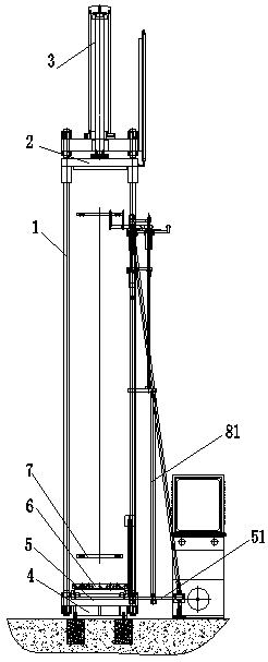
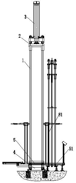
[0014] The present invention includes at least two guide rods 1 that are vertically arranged correspondingly and play a guiding role. An upper pressing plate 2 that can move up and down along the guiding rod 1 is arranged above the guiding rods 1 . There is an upper pressing plate driving device 3 for driving the upper pressing plate 2 to move up and down;
[0015] The bottom of the guide rod 1 is fixedly provided with a lower platen 4, the lower platen 4 is provided with a movable template 5, the movable template 5 can move up and down along the guide rod 1, and the upper part of the movable template 5 is provided with a The formwork 5 forms a fixedly connected flange connecting plate 6 for connecting a flange 7 .
[0016] A movable template driving device 8 is also provided to drive the movable template 5 to move up and down. The movable template driving device 8 is connected to the movable template 5 and drives the movable template 5 to move up and down.
[0017] A horizon...
PUM
 Abstract
Description
Claims
Application Information
 - R&D Engineer
- R&D Manager
- IP Professional
- Industry Leading Data Capabilities
- Powerful AI technology
- Patent DNA Extraction
Browse by: Latest US Patents, China's latest patents, Technical Efficacy Thesaurus, Application Domain, Technology Topic, Popular Technical Reports.
© 2024 PatSnap. All rights reserved.Legal|Privacy policy|Modern Slavery Act Transparency Statement|Sitemap|About US| Contact US: help@patsnap.com