
UPS power supply for oil field gas purification device

A gas purification device and oil field technology, applied in circuit devices, emergency power supply arrangements, electrical components, etc., can solve the problems of unstable power supply, entering into the power supply cabinet, inconvenient handling, etc., to improve practicability, improve safety, Guaranteed effect of stability

Active Publication Date: 2019-04-09
孙绍武
View PDF9 Cites 0 Cited by
  • Summary
  • Abstract
  • Description
  • Claims
  • Application Information

AI Technical Summary

Problems solved by technology

[0004] The invention provides a UPS power supply for an oil field gas purification device, which has the advantages of being easy to carry, easy to store the handling tools, and good heat dissipation effect, and solves the problem of the existing UPS power supply. It is very inconvenient to carry, some power supplies are moved by installing rollers at the bottom, but this will cause the center of gravity of the power supply to move up, which will easily cause instability of the power supply. In addition, the power supply will generate a lot of heat when it is working, so it needs to be checked Heat dissipation, however, when the current heat dissipation structure is performing heat dissipation, it is easy for external dust to enter the power cabinet along the vent hole, resulting in the accumulation of dust inside the cabinet

Method used


Image

  • UPS power supply for oil field gas purification device
  • UPS power supply for oil field gas purification device
  • UPS power supply for oil field gas purification device

Examples


Embodiment Construction

[0026] The following will clearly and completely describe the technical solutions in the embodiments of the present invention with reference to the accompanying drawings in the embodiments of the present invention. Obviously, the described embodiments are only some, not all, embodiments of the present invention. Based on the embodiments of the present invention, all other embodiments obtained by persons of ordinary skill in the art without making creative efforts belong to the protection scope of the present invention.

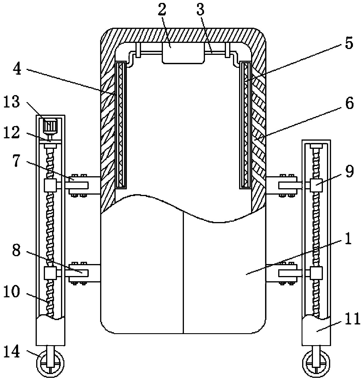
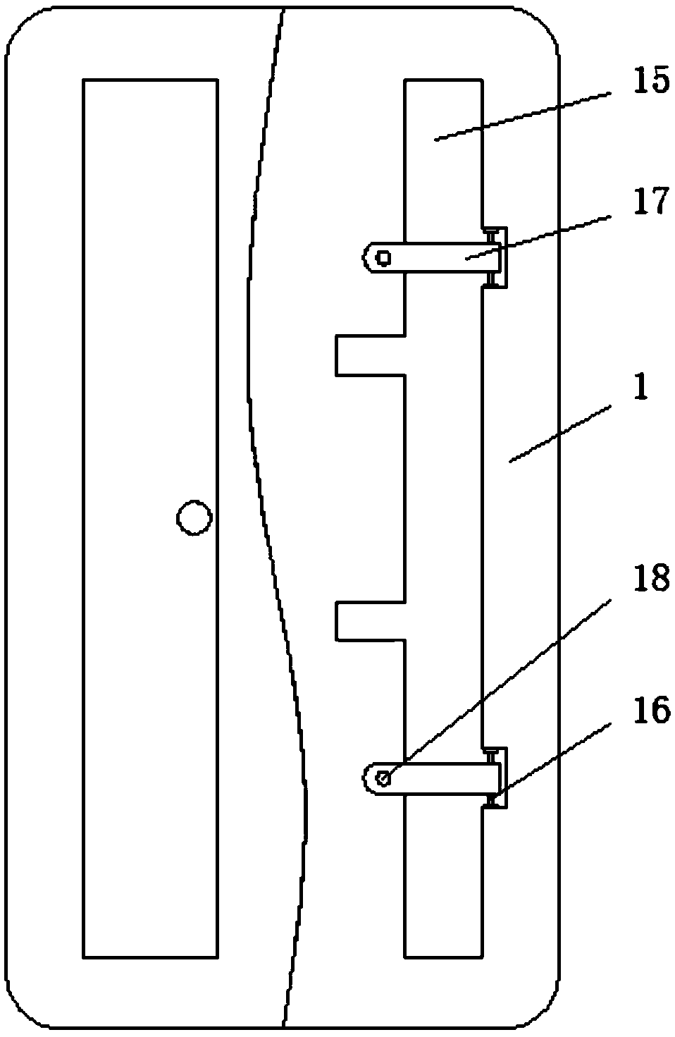
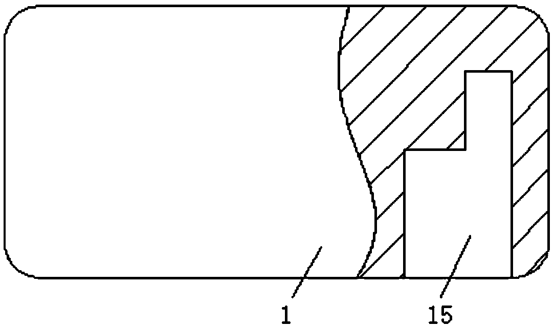
[0027] see Figure 1-7, a UPS power supply for an oil field gas purification device, comprising a power cabinet 1, a fan 2 is fixedly installed in the middle of the inner cavity top of the power cabinet 1, one side of the fan 2 is connected through one end of a connecting pipe 3, and the number of the connecting pipe 3 is Two, and one end of the two connecting pipes 3 is fixedly connected to the top of the dust filter box 4, one side of the dust filter box 4 i...


PUM


Abstract

The invention relates to the technical field of the UPS power supply, and discloses a UPS power supply for an oil field gas purification device. The UPS power supply comprises a power supply cabinet,a fan is fixedly arranged in the middle of a top end of an inner cavity of the power supply cabinet, one side of the fan and one end of each connecting pipe are in penetrating connection, and the amount of the connecting pipe is two, one end of each connecting pipe is fixedly connected with the top of each dust filtration box, one side of each dust filtration box is fixedly arranged at one side ofthe inner cavity of the power supply cabinet, and a filter screen is movably arranged in the inner cavity of each dust filtration box; and vent holes are formed on two sides of the power supply cabinet. Through the cooperative use of conveying rods, mounting blocks, connecting blocks, sliding blocks, a motor, a spacing board and rollers, the motor drives a threaded rod to rise the power supply cabinet to separate from the ground, and then moves the conveying rods to realize the movement of the power supply cabinet, the problem that the power supply is unstable since the power supply center ofgravity is moved up by mounting the rollers at the bottom of the power supply cabinet is avoided, and the practicability is improved.

Description

technical field [0001] The invention relates to the technical field of UPS power supply, in particular to a UPS power supply for an oilfield gas purification device. Background technique [0002] UPS, uninterruptible power supply, is a system device that connects the battery with the host, and converts direct current into mains power through a module circuit such as the host inverter. It is mainly used for a single computer, computer network system or other power electronic equipment such as Solenoid valves, pressure transmitters, etc. provide stable and uninterrupted power supply. [0003] The existing UPS power supply, due to the relatively large specifications of the UPS power supply, makes it extremely inconvenient to carry. Some power supplies are moved by installing rollers at the bottom. In addition, the power supply will generate a lot of heat when it is working, so it needs to be dissipated. However, when the current heat dissipation structure is dissipating heat, ...

Claims


Application Information

Patent Timeline
IPC IPC(8): H02J9/06H05K7/20
CPCH02J9/06H05K7/20909
Inventor 不公告发明人
Owner 孙绍武
Learn More