Simple charging power supply for three-phase four-wire combined transformer
A combination of transformers and three-phase four-wire technology, applied to electrical components, output power conversion devices, conversion equipment that can be converted to DC without intermediate conversion, etc., can solve the problems of heavy weight, large volume, etc., and achieve operation Ease of use, light product weight, and cost reduction effects
- Summary
- Abstract
- Description
- Claims
- Application Information
AI Technical Summary
Problems solved by technology
Method used
Image

Examples
Embodiment 1
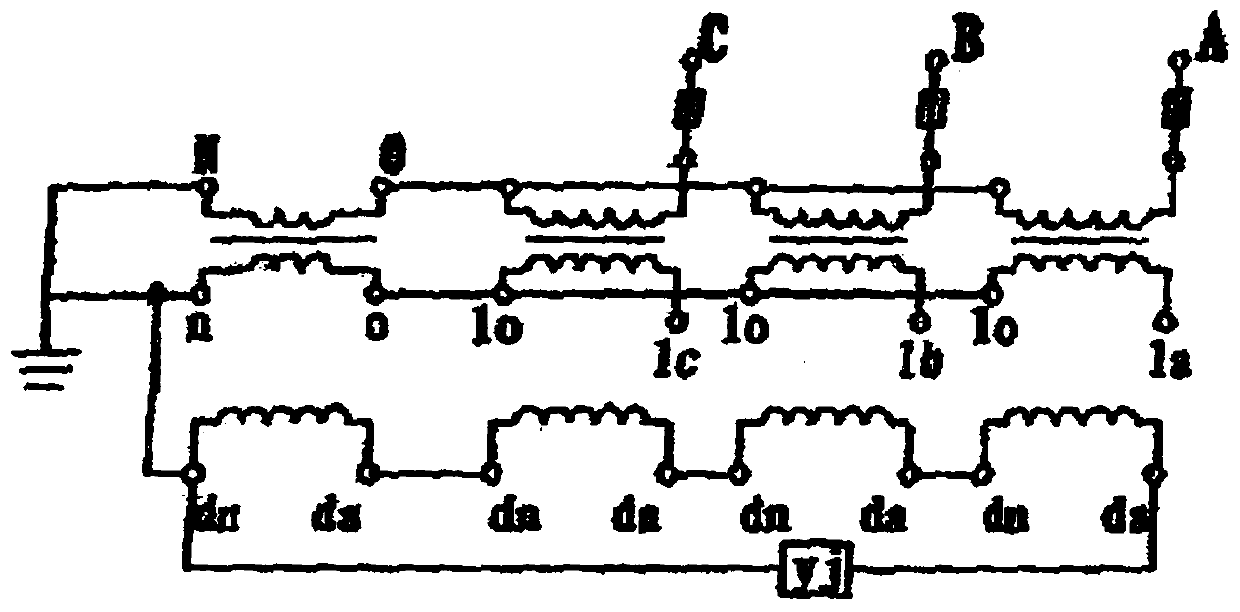
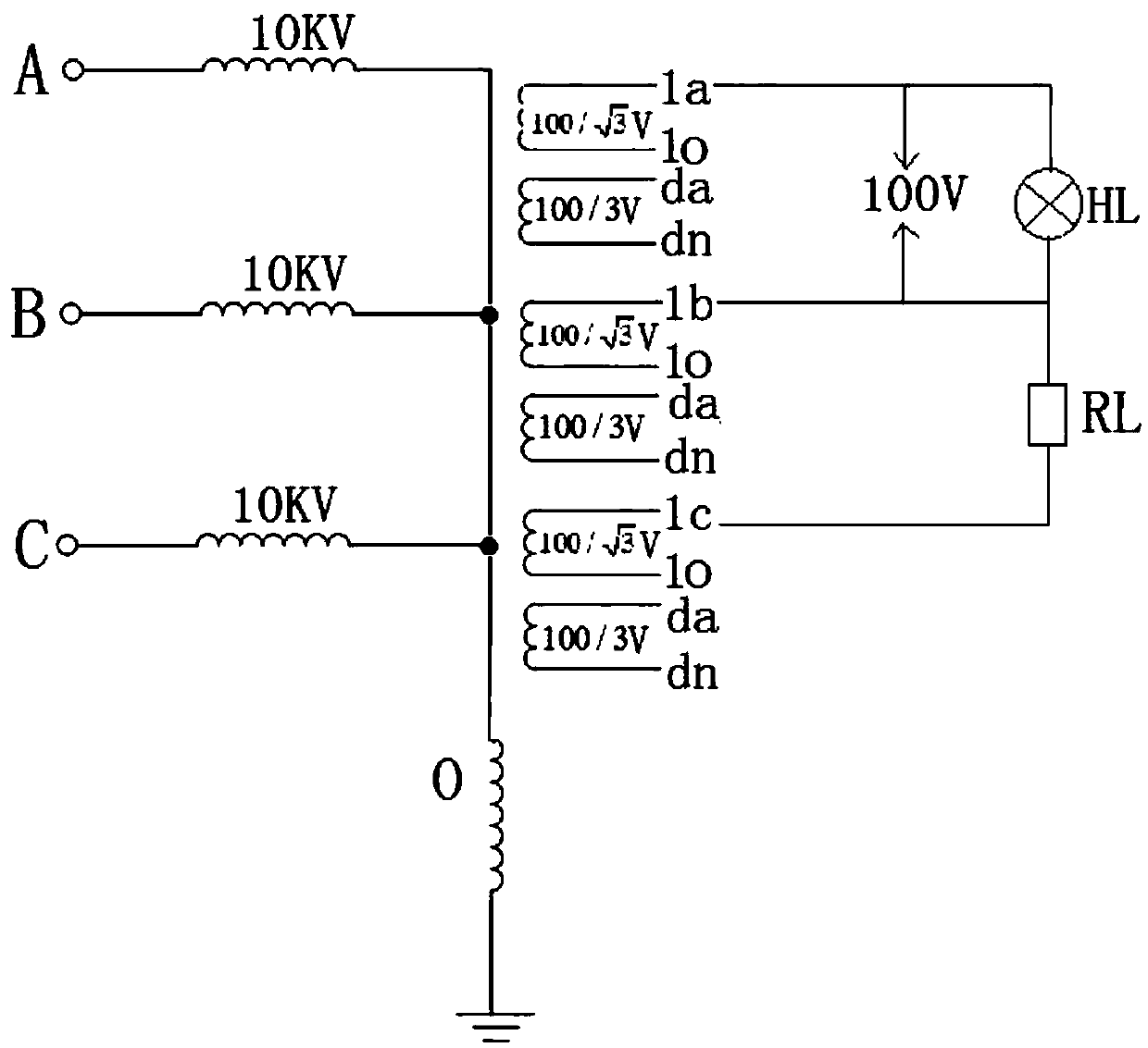
[0023] Such as figure 1 , figure 2 As shown, a simple charging power supply for a three-phase four-wire combined transformer includes a primary side end and a secondary side end, and the windings of the primary side end and the secondary side end are respectively wound on the iron core The primary side and the secondary side; the primary side includes A-phase, B-phase, and C-phase voltage input terminals, and the output terminals corresponding to the A-phase, B-phase, and C-phase voltage input terminals are connected to the neutral line O and then grounded ; The secondary-side terminal includes secondary-side input terminals a, b, and c corresponding to the A-phase, B-phase, and C-phase voltage input terminals of the primary-side terminal, respectively, and the secondary-side input terminals a, b The output ends of , c are all connected to the center line O and then grounded, and form secondary sides 1a, 1o, 1b, 1o and 1c, 1o; also include da, dn terminals, and are respectiv...
Embodiment 2
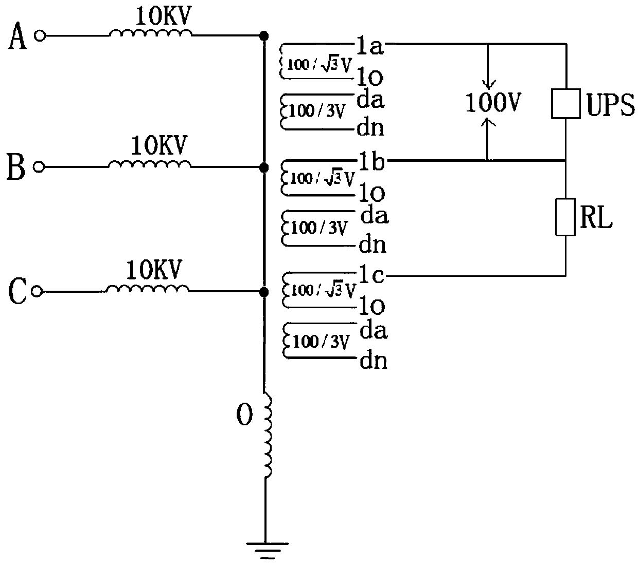
[0035] Such as figure 1 , image 3 As shown, the difference between this embodiment and Embodiment 1 is that in this embodiment, the charging terminal is used to connect the charging load to charge the UPS, and the power of the charging terminal UPS and the load RL are equal ; The load RL is used to ensure the balance of the three-phase voltage, prevent the product from resonating, and prevent the product from being burned;
[0036] In addition, adopt the first (1) connection method between the charging terminal UPS and the load RL, directly connect the charging terminal UPS at the 1a and 1b terminals, and connect the 1b and 1c terminals (or 1a and 1c terminals) to the load RL. .
Embodiment 3
[0038] Such as Figure 1 to Figure 3 As shown, the difference between this embodiment and Embodiment 1 and Embodiment 2 is that the lead wire connection mode between the charging terminal (the charging load UPS or the light bulb HL) and the load RL adopts the second (2) charging terminal UPS and the load RL In the connection mode, the ac terminals of the secondary side input terminals a, b, c are directly connected to the charging terminals, and the ab or bc terminals are used to connect to the load RL;
[0039] It is also possible to charge the charging load UPS, or simulate the light bulb HL, and use a voltmeter to test that the actual voltage at both ends of the charging terminal (charging load UPS or light bulb HL) is 98.6V, which is a normal error compared with the required rated voltage of 100V Within the allowable range, meet the specified requirements of 100V power supply.
PUM
 Abstract
Description
Claims
Application Information
 - R&D
- Intellectual Property
- Life Sciences
- Materials
- Tech Scout
- Unparalleled Data Quality
- Higher Quality Content
- 60% Fewer Hallucinations
Browse by: Latest US Patents, China's latest patents, Technical Efficacy Thesaurus, Application Domain, Technology Topic, Popular Technical Reports.
© 2025 PatSnap. All rights reserved.Legal|Privacy policy|Modern Slavery Act Transparency Statement|Sitemap|About US| Contact US: help@patsnap.com