A kind of head-mounted display device and lens adjustment method

A head-mounted display and lens technology, which is applied to eye testing equipment, retinoscopy, medical science, etc., can solve the problems of inaccurate adjustment results and inability to adjust the display device accurately, and achieve the effect of improving the adjustment accuracy

Active Publication Date: 2021-07-23
BEIJING 7INVENSUN TECH
View PDF5 Cites 0 Cited by
  • Summary
  • Abstract
  • Description
  • Claims
  • Application Information

AI Technical Summary

Problems solved by technology

[0003] In order to meet the various needs of users, the existing head-mounted display device can adjust the distance between the lens and the display screen, so that users with ametropia can use the head-mounted display device, but the head-mounted display device in the prior art The traditional display device cannot be adjusted accurately to adapt to the normal use of users with refractive errors. When users with refractive errors use it, if they want to obtain clear images from the display screen, they can only adjust the distance between the display screen and the lens through subjective judgment. distance, so the adjustment result is inaccurate

Method used


Image

  • A kind of head-mounted display device and lens adjustment method
  • A kind of head-mounted display device and lens adjustment method
  • A kind of head-mounted display device and lens adjustment method

Examples


Embodiment 1

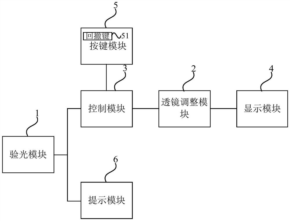
[0040] Figure 1a It is a schematic structural diagram of a head-mounted display device provided by Embodiment 1 of the present invention. This embodiment is applicable to the situation of automatically adjusting the lens in the head-mounted display device, such as Figure 1a As shown, the head-mounted display device may specifically include: an optometry module 1, a lens adjustment module 2, a control module 3, and a display module 4. The lens adjustment module 2 may specifically include at least two lenses (not shown in the figure), and the following Describe its structure and function.

[0041] The output end of the optometry module 1 is connected to the input end of the control module 3 , and the output end of the control module 3 is connected to the control end of the lens adjustment module 2 .

[0042] The optometry module 1 detects the diopter of the user's eyes, and sends the diopter to the control module 3. The control module 3 generates a movement command according to...

Embodiment 2

[0082] figure 2 It is a flow chart of a lens adjustment method provided by Embodiment 2 of the present invention. This embodiment is applicable to the situation of automatically adjusting the lens in a head-mounted display device. This method can be executed by a head-mounted display device. The device It can be realized by means of software and / or hardware. like figure 2 As shown, the method specifically includes the following steps:

[0083] Step 210: Detect the diopter of the user's eyes through the optometry module, and send the diopter to the control module.

[0084] Step 220, the control module generates a movement command according to the diopter, and sends the movement command to the electric push rod in the lens adjustment module.

[0085] Step 230 : Control the movement of the corresponding lens in the lens adjustment module according to the movement instruction through the electric push rod, so that the lens falls into the display module through the first housi...


PUM


Abstract

The invention discloses a head-mounted display device and a lens adjustment method. The device includes: an optometry module, a lens adjustment module, a control module and a display module. The lens adjustment module includes at least two lenses; the output end of the optometry module is connected to the input end of the control module, and the output end of the control module is connected to the lens adjustment module. The optometry module detects the diopter of the user's eyes and sends the diopter to the control module. The control module generates a movement command according to the diopter and sends the movement command to the lens adjustment module. The lens adjustment module controls the corresponding lens to move according to the movement command. Let the lens drop into the display module. The embodiments of the present invention improve the adjustment accuracy of the head-mounted display device.

Description

technical field [0001] Embodiments of the present invention relate to wearable device technology, in particular to a head-mounted display device and a lens adjustment method. Background technique [0002] The head-mounted display device is a new technology in modern display technology. The development of high-resolution image reconstruction technology, the perfection of binary optics theory and design, and the maturity of holographic technology have opened up new possibilities for the design of head-mounted display devices. The new approach has also brought more and more head-mounted display devices into the public eye. [0003] In order to meet the various needs of users, the existing head-mounted display device can adjust the distance between the lens and the display screen, so that users with ametropia can use the head-mounted display device, but the head-mounted display device in the prior art The traditional display device cannot be adjusted accurately to adapt to the ...

Claims


Application Information

Patent Timeline
Patent Type & Authority Patents(China)
IPC IPC(8): A61B3/103G02B27/01
CPCA61B3/0008A61B3/005A61B3/0075A61B3/103G02B27/0172
Inventor 黄通兵
Owner BEIJING 7INVENSUN TECH
Why Eureka
Try Eureka