Method for adjusting height and position of magnetic head

An adjustment method and magnetic head technology, which are applied in the arrangement of recording heads, configuration/installation of recording heads, driving/moving of recording heads, etc., can solve the problem of inconsistent adjustment accuracy of the height position of the magnetic head, uneven recovery of the substrate 112, and difficulty in predicting the substrate 112. Problems such as bending direction and bending amount, to achieve the effect of reducing the adjustment accuracy

Inactive Publication Date: 2006-01-18
ALPS ALPINE CO LTD
View PDF4 Cites 0 Cited by
  • Summary
  • Abstract
  • Description
  • Claims
  • Application Information

AI Technical Summary

Problems solved by technology

[0008] However, since the substrate 112 is generally a metal product, when the extrusion action by the punch 122 is stopped, an elastic recovery phenomenon returning to the original state caused by the elasticity of the substrate itself will occur.
The recovery amount of the substrate 11

Method used


Image

  • Method for adjusting height and position of magnetic head
  • Method for adjusting height and position of magnetic head
  • Method for adjusting height and position of magnetic head

Examples


Embodiment Construction

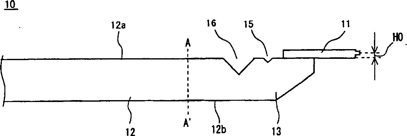
[0039] figure 1 It shows the magnetic head 10 before it is mounted on the rotary drum as the object of adjustment by the method of this invention. The magnetic head 10 has a magnetic head element 11 that performs recording and reproducing operations, and a substrate 12 that holds the magnetic head element 11 protruding from the tip of the magnetic head supporting surface 12 a.

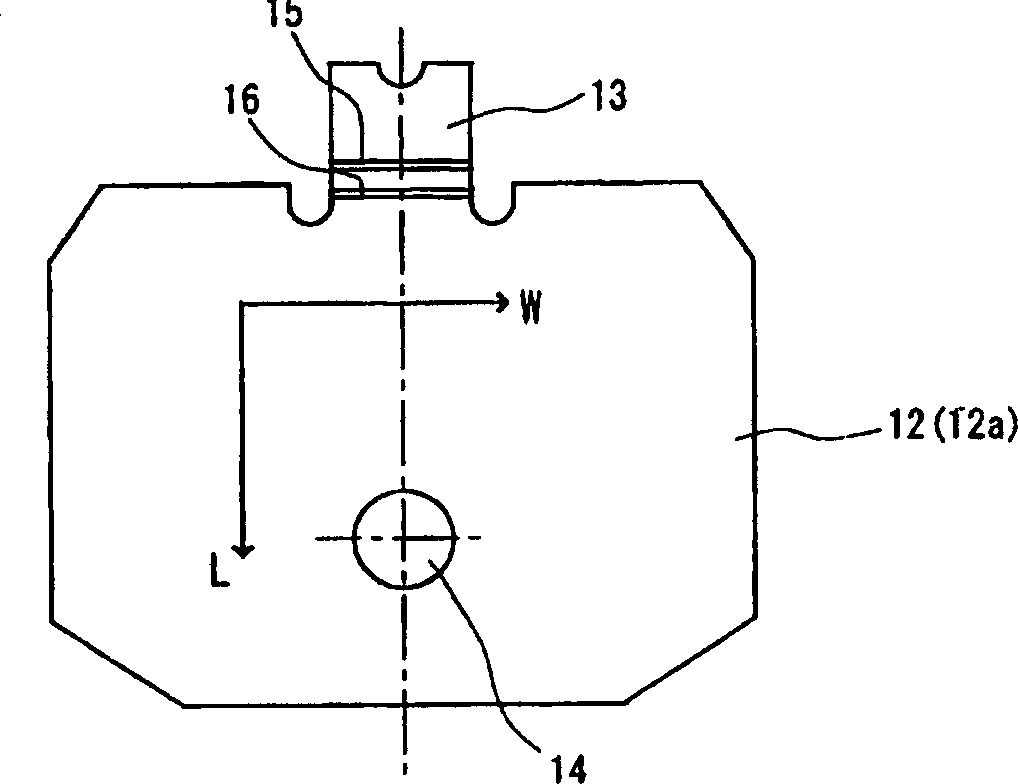
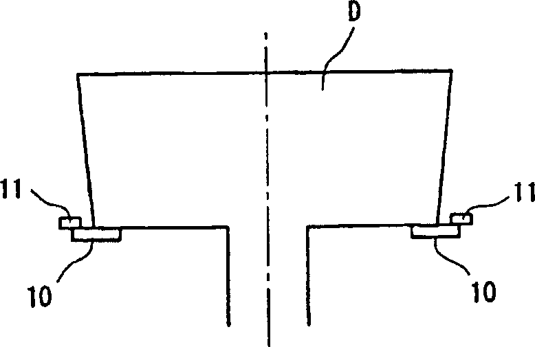
[0040] Such as figure 2 As shown, the substrate 12 is formed by a flat metal plate, and the metal plate has an elastic tongue part 13 at the top position to which the magnetic head element 11 is bonded and fixed, and a tongue part 13 at the center which is rotationally driven by a driving mechanism not shown. Rotating Drum D( image 3 ) Mounting holes 14 with free loading and unloading. figure 1 and Figure 4 The A-A' line shown by the middle dotted line is the bottom position of the semicircular space formed on the left and right sides of the elastic tongue part 13 in the figure. In this manua...


PUM


Abstract

To acquire a height positioning method of a magnetic head by which head height according to the pressing amount to a base plate is obtained, and variation of adjustment accuracy can be reduced.The height positioning method of a magnetic head includes a step to fix a magnetic head element to a front edge of a magnetic head supporting surface of the base plate in the state that it is made to project from the base plate; a step to hold the base plate by abutting the magnetic head supporting surface excluding a reference plane and a front edge of the base plate to a receiving block having a reference plane, and the head element and the front edge of the base board is made to project from the reference plane; and a step to adjust the height position of the magnetic head to the magnetic head supporting surface by sandwiching the base plate between receiving block reference plane to press from the pressure line set at an opposite face side of the magnetic head supporting surface to deform it.

Description

technical field [0001] The present invention relates to a method of adjusting the height position of a magnetic head mounted, for example, in video equipment. Background technique [0002] Generally, a VTR (Video Tape Recorder, Video Tape Recorder) device is equipped with a helical scanning magnetic head device having a pair of magnetic heads arranged at predetermined intervals on the outer peripheral surface of a rotating drum. In this magnetic head device, a pair of magnetic head elements slide on a magnetic recording medium (tape) by rotation of a rotary drum to record and reproduce video or audio. Conventionally, the adjustment of the head height position (the distance from the head support surface of the substrate to the end point of the magnetic gap region of the head element) is performed before or after mounting the head on the rotary drum. [0003] In the case of adjusting the head height position before mounting on the rotary head, such as Figure 6 As shown, unde...

Claims


Application Information

Patent Timeline
IPC IPC(8): G11B5/53G11B5/56
CPCG11B3/26G11B5/53G11B21/12G11B2005/0008
Inventor 山崎祐二
Owner ALPS ALPINE CO LTD
Why Eureka
Try Eureka