Mould for one-step molding steel ball in center position, and injection molding method

A center position, steel ball technology, applied in the field of built-in steel ball injection molding, can solve the problems of rough bonding, bonding marks at the upper and lower sphere bonding, low injection qualification rate, etc., to achieve good product quality, simple mechanism and action, and production. Efficient effect

Inactive Publication Date: 2019-04-12
SHENZHEN JINCAIHONG PLASTIC
View PDF3 Cites 1 Cited by
  • Summary
  • Abstract
  • Description
  • Claims
  • Application Information

AI Technical Summary

Problems solved by technology

[0002] In the injection molding industry, if it is necessary to perform injection molding on the outer surface of the steel ball so that the outer injection molded parts evenly wrap the sphere, two hemispherical shells are usually made through two molds, and then the steel ball is put into the two hemispherical shells, through glue or The two hemispherical shells are connected by high-frequency heat sealing. This injection molding method will cause obvious bonding marks at the joints of the upper and lower spheres. The joints of the entire injection molded product are relatively rough and cannot achieve the required smoothness; There is another injection molding method, which is to inject half of the mold through a mold with a relatively complex structure, then put in steel balls, continue to inject the other half, and finally complete the injection molding of the entire product. Although the surface smoothness of this type of injection molding method meets the requirements, it cannot guarantee injection molding. Parts evenly wrap the sphere, this kind of injection molding method has a low injection pass rate and is not conducive to large-scale promotion

Method used


Image

  • Mould for one-step molding steel ball in center position, and injection molding method
  • Mould for one-step molding steel ball in center position, and injection molding method
  • Mould for one-step molding steel ball in center position, and injection molding method

Examples


Embodiment Construction

[0026] The present invention will be further described in detail below in conjunction with the embodiments and the accompanying drawings, but the embodiments of the present invention are not limited thereto.

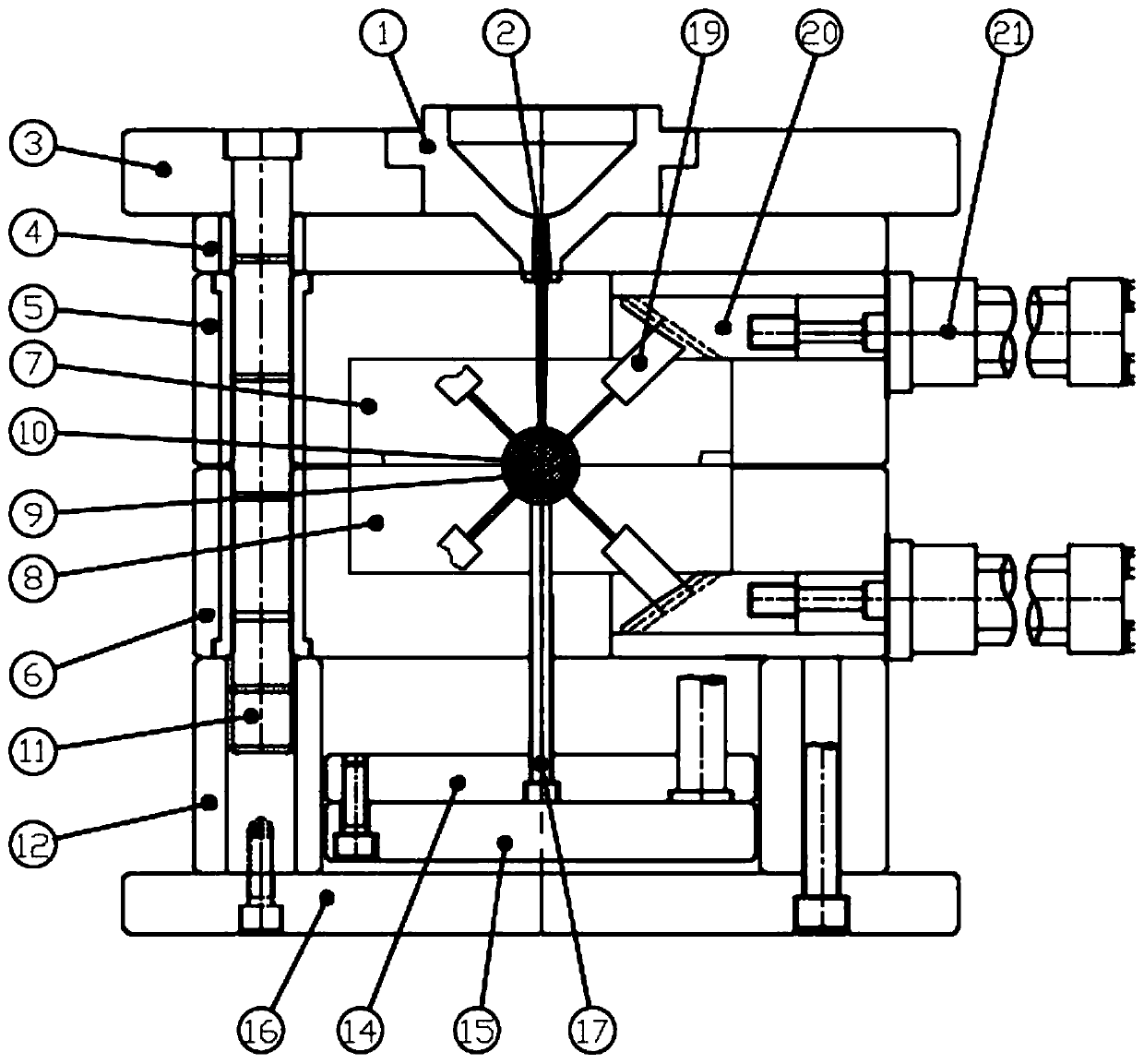
[0027] Such as figure 1 As shown, a mold for one-time molding of steel balls at the central position includes: an oil cylinder, a positioning insert, a positioning needle, a front mold panel 3, a rear mold bottom plate 16, a nozzle plate 4 and an injection mold group, and the injection mold The group includes: A plate 5, B plate 6, front mold core 7 and rear mold core 8, the middle part of the lower surface of A plate 5 has a first groove and the front mold core 7 is fixedly installed in the first groove, and B plate 6. There is a second groove in the middle of the upper surface and a rear mold core 8 is fixedly installed in the second groove. The lower surface of the front mold core 7 is provided with a first semicircular groove, and the upper surface of the rear mold c...


PUM

PropertyMeasurementUnit
tackinessaaaaaaaaaa

Abstract

The invention relates to the technical field of built-in steel ball injection molding, in particular to a mould for one-step molding a steel ball in the center position, and an injection molding method. The mould comprises oil cylinders, a slide insert, a slide needle, a front mould panel, a back mould bottom plate, a stripper plate and an injection molding module, wherein the injection molding module comprises a plate A, a plate B, a front mould core and a back mould core; a first semicircular groove is formed in the lower surface of the front mould core; a second semicircular groove is formed in the upper surface of the back mould core; the oil cylinders are arranged on the plate A and the plate B and control, and control the slide needle to stretch out and draw back through the slide insert; the slide insert and the slide needle are embedded into the injection molding module; and the slide needle stretches into an injection molding cavity. According to the mould for one-step moldingthe steel ball in the center position provided by the invention, the slide needle is introduced for positioning the steel ball, so that the steel ball is ensured to be located in the center positionof the injection molding cavity, the injection molding outer surface is smooth, and the smoothness of the product is ensured; and by adopting the structure, the problems that according to an existinginjection molding machine mould, the steel ball cannot be placed in the center of the injection molding center, and the product surface is not smooth are solved successfully.

Description

technical field [0001] The invention relates to the technical field of injection molding with built-in steel balls, in particular to a mold and an injection molding method for one-time molding of steel balls at a central position. Background technique [0002] In the injection molding industry, if it is necessary to perform injection molding on the outer surface of the steel ball so that the outer injection molded parts evenly wrap the sphere, two hemispherical shells are usually made through two molds, and then the steel ball is put into the two hemispherical shells, through glue or The two hemispherical shells are connected by high-frequency heat sealing. This injection molding method will cause obvious bonding marks at the joints of the upper and lower spheres. The joints of the entire injection molded product are relatively rough and cannot achieve the required smoothness; There is another injection molding method, which is to inject half of the mold through a mold with ...

Claims


Application Information

Patent Timeline
Patent Type & Authority Applications(China)
IPC IPC(8): B29C45/33B29C45/14B29C45/16B29C33/12B29C45/40
CPCB29C45/14065B29C45/1615B29C45/33B29C45/4005
Inventor 吴军军陈恩辉
Owner SHENZHEN JINCAIHONG PLASTIC
Why Eureka
Try Eureka