Vehicle air conditioning system with overhead condenser

A vehicle air conditioner and condenser technology, which is applied to vehicle parts, air handling equipment, heating/cooling equipment, etc., can solve the problems of poor versatility, influence, single assembly relationship between condenser parts and evaporator parts, etc., and improve the use of The effect of versatility

Pending Publication Date: 2019-04-12
CHANGZHOU CHANGFA REFRIGERATION TECH CO LTD
View PDF0 Cites 0 Cited by
  • Summary
  • Abstract
  • Description
  • Claims
  • Application Information

AI Technical Summary

Problems solved by technology

[0002] Generally, in order to prevent the condenser parts from being blocked between the intercooler and the compressor, and the condenser parts affect the heat dissipation of the compressor by the intercooler, the condenser parts are usually fixedly installed on the top of the car body through an additional housing. However, because the assembly relationship between the condenser part and the evaporator part is relatively simple, the versatility is poor, and it is difficult to meet the technical requirements of the roof installation

Method used


Image

  • Vehicle air conditioning system with overhead condenser
  • Vehicle air conditioning system with overhead condenser
  • Vehicle air conditioning system with overhead condenser

Examples


Embodiment 1

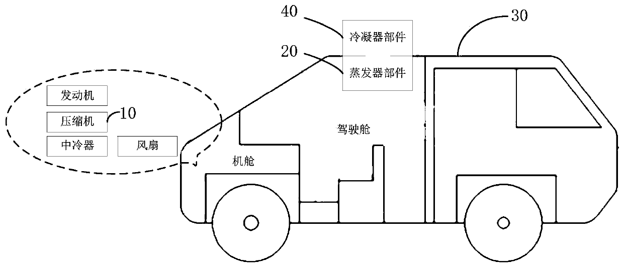
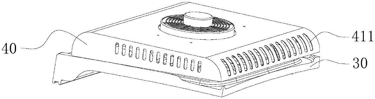
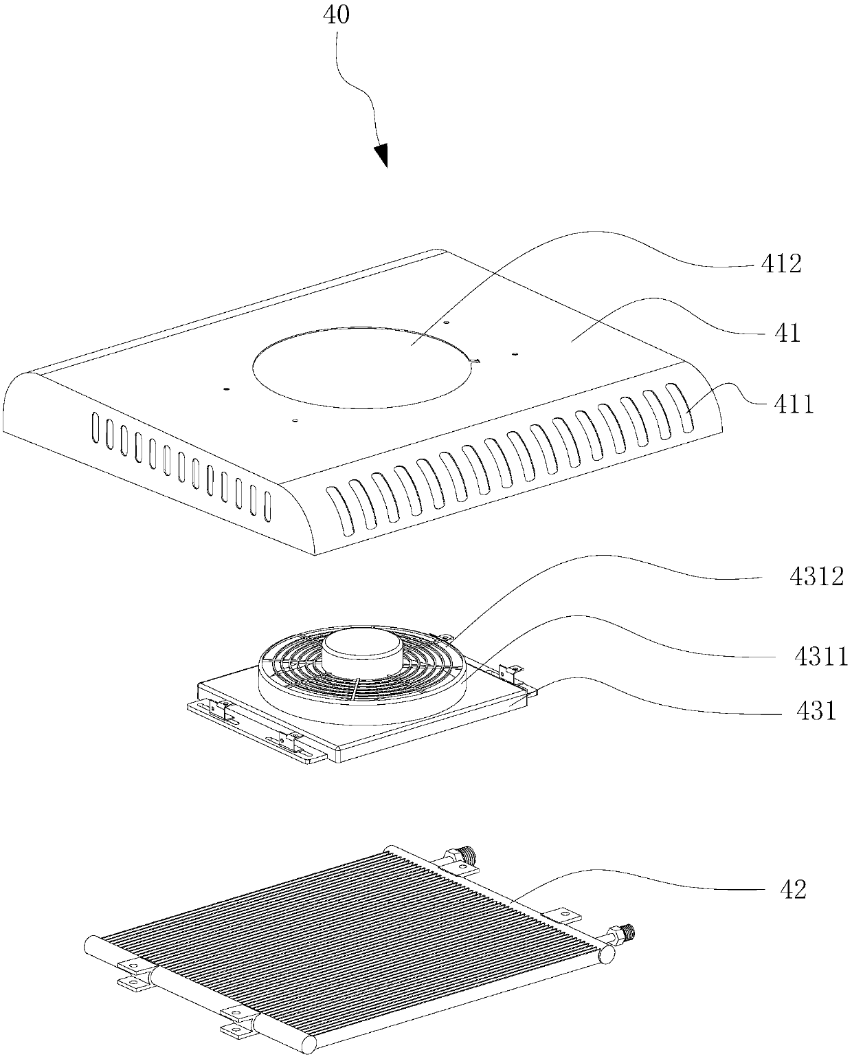
[0034] Please see Figure 1-Figure 3 , Embodiment 1 of the present invention provides a vehicle air-conditioning system with an overhead condenser. The vehicle air-conditioning system with an overhead condenser includes a compressor (not shown) installed in the vehicle and an expansion valve The evaporator part (not shown) and the condenser part 40 directly installed on the top of the car body 30, the compressor, the condenser part 40 and the evaporator part are connected in sequence to form a closed circulation pipeline, and the compressor A refrigerant is provided in the pipelines connected in sequence to the condenser part 40 and the evaporator part, and the type of refrigerant includes but not limited to Freon.

[0035] The compressor is installed in the engine compartment, and the evaporator part is installed in the cockpit. Specifically, the evaporator part can be integrally assembled with the condenser part 40. Specifically, the evaporator part can be hoisted on the con...

Embodiment 2

[0047] Please also see Figure 9The main difference between the condenser part 40 provided in the second embodiment and the condenser part 40 in the first embodiment is that the evaporator part 20 is installed on the condenser connecting part 421, and the condenser connecting part 421 adopts a sliding connection or the like and condensing The device bracket 44 is movably connected. Specifically, the number of condenser connectors 421 is two, and the two condenser connectors 421 are relatively arranged on both sides of the condenser 42, and each condenser connector 421 is provided with a notch 442 and an air inlet duct. 311 are connected to the air inlet 4211, and each condenser bracket 44 is provided with a sliding groove 443 that is matched with the condenser connecting piece 421 along the axial direction of the condenser bracket 44, that is, one of the condenser connecting pieces 421 is placed in a sliding groove 443, another condenser connector 421 is placed in another sli...


PUM


Abstract

The invention provides a vehicle air conditioning system with an overhead condenser. The vehicle air conditioning system with the overhead condenser is used for a vehicle; the vehicle comprises a vehicle body with a driving cab and an engine cab, and an engine which is mounted in the engine cab; the vehicle air conditioning system with the overhead condenser comprises a compressor and an evaporator part which are mounted in the vehicle body and a condenser part which is connected with the top of the vehicle body; the compressor is connected with the engine. The vehicle air conditioning systemwith the overhead condenser provided by the invention has better universality.

Description

technical field [0001] The invention relates to the technical field of air conditioning systems, in particular to a vehicle air conditioning system with an overhead condenser. Background technique [0002] Generally, in order to prevent the condenser parts from being blocked between the intercooler and the compressor, and the condenser parts affect the heat dissipation of the compressor by the intercooler, the condenser parts are usually fixedly installed on the top of the car body through an additional housing. However, because the assembly relationship between the condenser part and the evaporator part is relatively simple, the versatility is poor, and it is difficult to meet the technical requirements for roof installation. Contents of the invention [0003] Based on this, it is necessary to address the above-mentioned problems and provide a vehicle air-conditioning system with an overhead condenser with good versatility. [0004] A vehicle air-conditioning system with...

Claims


Application Information

Patent Timeline
Patent Type & Authority Applications(China)
IPC IPC(8): B60H1/00
CPCB60H1/00321B60H1/00507
Inventor 黄晓峰朱宇晨谈峰明唐晓鹏
Owner CHANGZHOU CHANGFA REFRIGERATION TECH CO LTD
Why Eureka
Try Eureka