Sewage purification disposal device
A treatment device and sewage purification technology, applied in water/sewage treatment, water/sludge/sewage treatment, chemical instruments and methods, etc., can solve problems such as difficult cleaning and blockage of grilles
- Summary
- Abstract
- Description
- Claims
- Application Information
AI Technical Summary
Problems solved by technology
Method used
Image
Examples
specific Embodiment approach 1
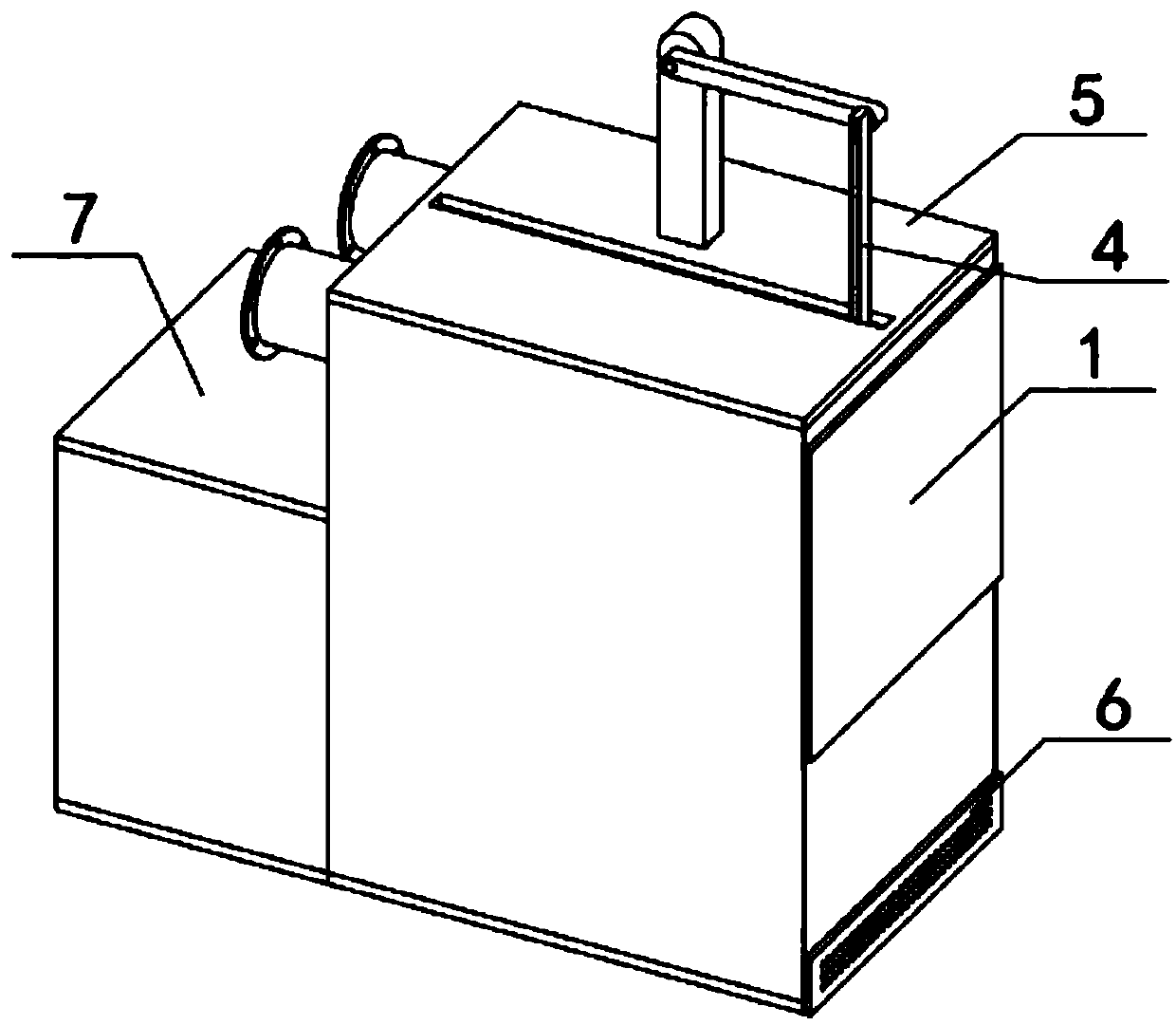
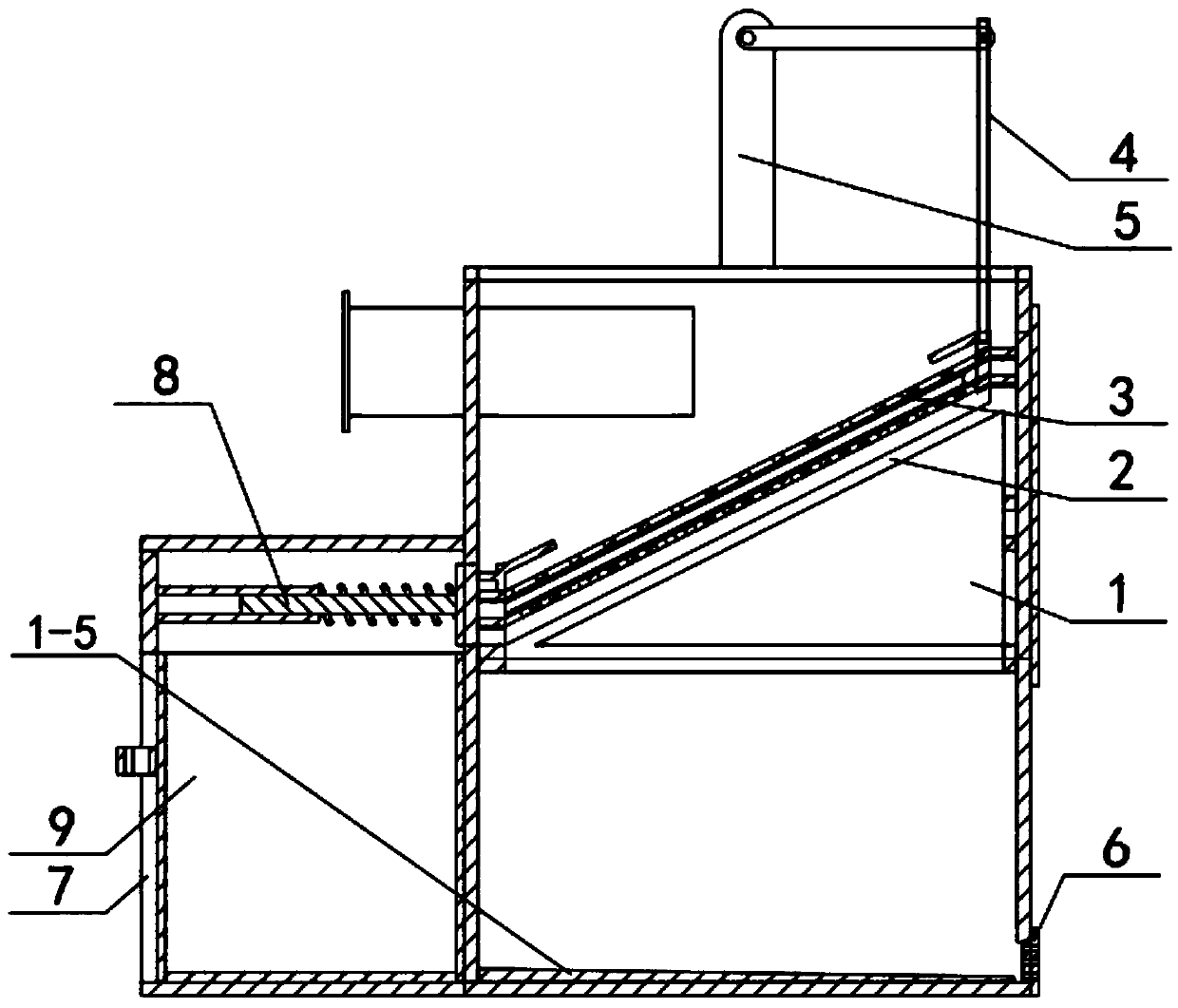
[0033] Such as Figure 1-13 As shown, a sewage purification treatment device includes a box body I1, a mounting frame 2, a self-cleaning filter mechanism 3, a transmission mechanism 4, a power source 5, a fine grid 6, a box body II7, an automatic blocking member 8 and a recovery box 9. A mounting frame 2 is placed in the box I1, a self-cleaning filter mechanism 3 is fixedly connected to the mounting frame 2, a transmission mechanism 4 is fixedly connected to the self-cleaning filter mechanism 3, and the transmission mechanism 4 is fixedly connected to the power source 5, The power source 5 is fixedly connected to the upper end of the box body I1, the fine grid 6 is fixedly connected to the right side of the lower end of the box body I1, the box body II7 is fixedly connected to the left end of the box body I1, and the automatic blocking member 8 is slidably connected to the box body II7 On and in contact with the box body I1, the recovery box 9 is located in the box body II7. ...
specific Embodiment approach 2
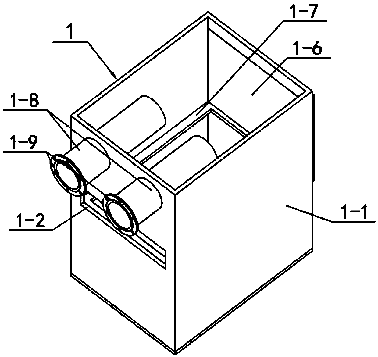
[0034] Such as Figure 1-13As shown, the box body I1 includes a box body I1-1, a sewage outlet 1-2, a drain outlet 1-3, a bottom plate I1-4, a collector plate 1-5, a packaging member 1-6, and a support frame 1-7 , water inlet pipe 1-8 and flange 1-9, the middle side of the left end of the box main body I1-1 is provided with a sewage outlet 1-2, and the lower side of the right end of the box main body I1-1 is provided with a drain port 1-3, the box main body The lower end of Ⅰ1-1 is fixedly connected with the bottom plate Ⅰ1-4, the upper end of the bottom plate Ⅰ1-4 is fixedly connected with the current collecting plate 1-5, the packaging component 1-6 is fixedly connected with the upper side of the right end of the box main body Ⅰ1-1, and the supporting frame 1 -7 is fixedly connected to the middle end of the tank main body Ⅰ1-1, and there are two water inlet pipes 1-8. The left end of each is fixedly connected with a flange 1-9. The collecting plate 1-5 is to make the twice...
specific Embodiment approach 3
[0035] Such as Figure 1-13 As shown, the mounting frame 2 includes a mounting frame body 2-1, a carrier plate I2-2, a carrier plate II2-3, a slide rail I2-4, a slide rail II2-5, a connecting plate 2-6 and a straight notch 2 -7, there are two carrier boards I2-2 and carrier board II2-3, and one carrier board I2-2 and one carrier board II2-3 are fixedly connected to the upper side of the left end of the mounting frame main body 2-1 , the carrier board I2-2 is located at the upper end of the carrier board II2-3, and the upper side of the right end of the installation frame main body 2-1 is fixedly connected with another carrier board I2-2 and another carrier board II2-3, the carrier board I2 -2 is located at the upper end of the carrier plate II 2-3, the connecting plate 2-6 is fixedly connected to the right end of the mounting frame main body 2-1, and the connecting plate 2-6 is provided with a straight notch 2-7; the mounting frame main body 2 -1 is placed on the upper end of...
PUM
 Abstract
Description
Claims
Application Information
 - R&D
- Intellectual Property
- Life Sciences
- Materials
- Tech Scout
- Unparalleled Data Quality
- Higher Quality Content
- 60% Fewer Hallucinations
Browse by: Latest US Patents, China's latest patents, Technical Efficacy Thesaurus, Application Domain, Technology Topic, Popular Technical Reports.
© 2025 PatSnap. All rights reserved.Legal|Privacy policy|Modern Slavery Act Transparency Statement|Sitemap|About US| Contact US: help@patsnap.com


