Laser array test fixture

A technology of laser array and test fixture, which is applied in the direction of optical instrument test, machine/structural component test, instrument, etc., can solve problems such as failure to meet test requirements, easy short circuit, simple structure, etc., to improve optical debugging level and ensure electrical reliability effect

Active Publication Date: 2019-04-12
THE 13TH RES INST OF CHINA ELECTRONICS TECH GRP CORP
View PDF5 Cites 0 Cited by
  • Summary
  • Abstract
  • Description
  • Claims
  • Application Information

AI Technical Summary

Problems solved by technology

[0004] The purpose of the present invention is to provide a laser array test fixture to solve the technical problems that the existing single laser test tool in the prior art has a simple structure, is easy to short circuit, and cannot meet the test requirements.

Method used


Image

  • Laser array test fixture
  • Laser array test fixture
  • Laser array test fixture

Examples


Embodiment Construction

[0023] In order to make the technical problems, technical solutions and beneficial effects to be solved by the present invention clearer, the present invention will be further described in detail below in conjunction with the accompanying drawings and embodiments. It should be understood that the specific embodiments described here are only used to explain the present invention, not to limit the present invention.

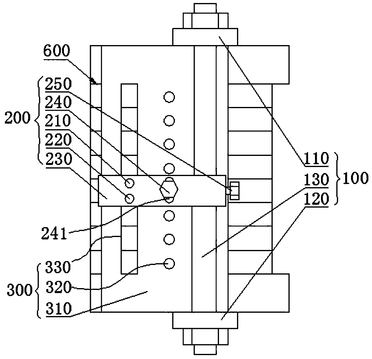
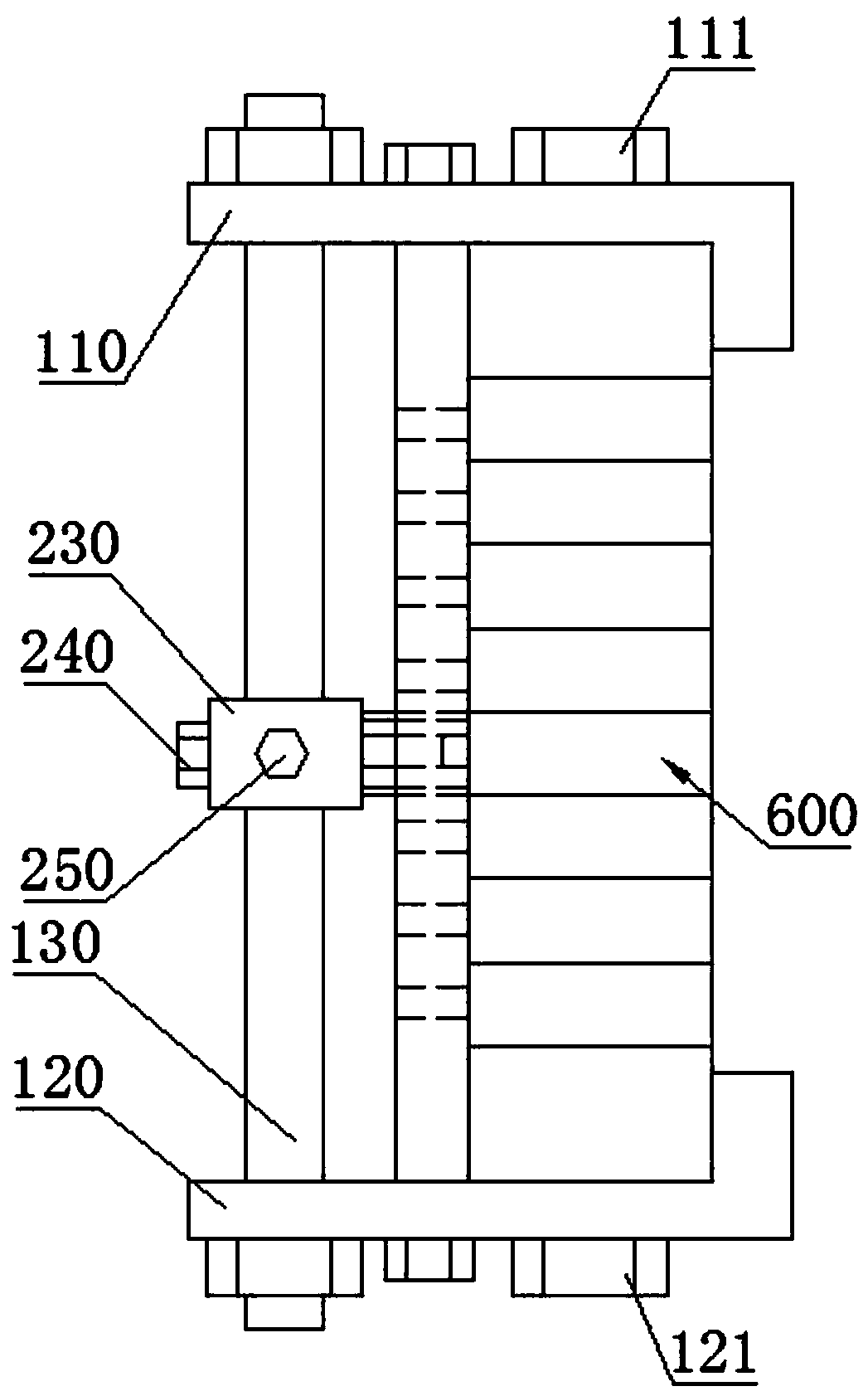
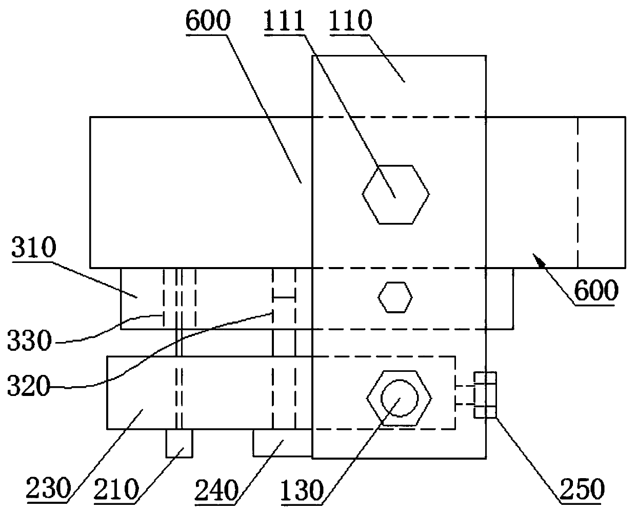
[0024] Please also refer to Figure 1 to Figure 3 , the laser array test fixture provided by the present invention will now be described. The laser array test fixture includes a clamping assembly 100 for clamping the laser array 600 from the upper and lower sides, a sliding block assembly 200 that slides and fits with the clamping assembly 100 in the up and down direction, and the board surface is arranged in the up and down direction and is used for fixing In the positioning assembly 300 of the slider assembly 200, the slider assembly 200 is provided with a first...


PUM


Abstract

The invention provides a laser array test fixture, and relates to the technical field of photoelectric detection. The laser array test fixture includes a clamping assembly, a sliding block assembly and a positioning assembly, and the sliding block assembly is provided with a first electrode for being contacted and matched with the upper end of the side part of a single laser in a laser array and asecond electrode for being contacted and matched with the lower end of the side part of the single laser. According to the laser array test fixture, the laser array test fixture is fixed on the outerside of the laser array through the clamping assembly, the sliding block assembly is used for realizing displacement in the upper and lower directions of the laser array, and the positioning assemblyis used for locking the sliding block assembly in a fixed position; and the first electrode and the second electrode are used for being contacted with the upper end and the lower end of the side partof the single laser correspondingly to detect the optical quality, and electrical reliability of the single laser in the laser array and measurability of the one-by-one single lasers in the assembledlaser array are effectively ensured.

Description

technical field [0001] The invention belongs to the technical field of photoelectric detection, and more specifically relates to a laser array test fixture. Background technique [0002] Semiconductor laser arrays have been more and more widely used in laser processing, laser medical treatment, laser display and military applications, and are favored for their small size, light weight, high efficiency and reliability. In recent years, with the further maturity of high-power semiconductor laser products, industrial processing, military and other fields have further requirements for the optical consistency of semiconductor laser arrays. [0003] The optical consistency of a semiconductor laser array not only depends on the optical characteristics of a single laser itself, but also on the stress generated during the array assembly process. Therefore, in order to obtain optical characteristics that meet the requirements, it is necessary to perform optical adjustments to the ind...

Claims


Application Information

Patent Timeline
Patent Type & Authority Applications(China)
IPC IPC(8): G01M11/00
CPCG01M11/00
Inventor 邸丽婵
Owner THE 13TH RES INST OF CHINA ELECTRONICS TECH GRP CORP
Why Eureka
Try Eureka