A Multi-Carrier Waveform Design Method

A waveform design and multi-carrier technology, applied in the modulation carrier system, multi-frequency code system, digital transmission system, etc., can solve the problems of high peak-to-average power ratio of multi-carrier waveform, harmonic generation, out-of-band spectrum spread interference, etc.

Active Publication Date: 2021-05-14
UNIV OF ELECTRONICS SCI & TECH OF CHINA
View PDF4 Cites 0 Cited by
  • Summary
  • Abstract
  • Description
  • Claims
  • Application Information

AI Technical Summary

Problems solved by technology

However, multi-carrier waveforms tend to cause problems with relatively large peak-to-average power ratios.
That is to say, its value at certain moments is relatively large, which will cause the power amplifier at the receiving end to enter a nonlinear state, which will cause nonlinear distortion of the OFDM signal, generate harmonics, and cause more obvious out-of-band spectrum spread interference and in-band The signal diffuses, and finally leads to the performance degradation of the whole system
In low-power terminal communications such as the Internet of Things and Iot, the system loss caused by multi-carrier is more serious

Method used


Image

  • A Multi-Carrier Waveform Design Method
  • A Multi-Carrier Waveform Design Method

Examples


Embodiment

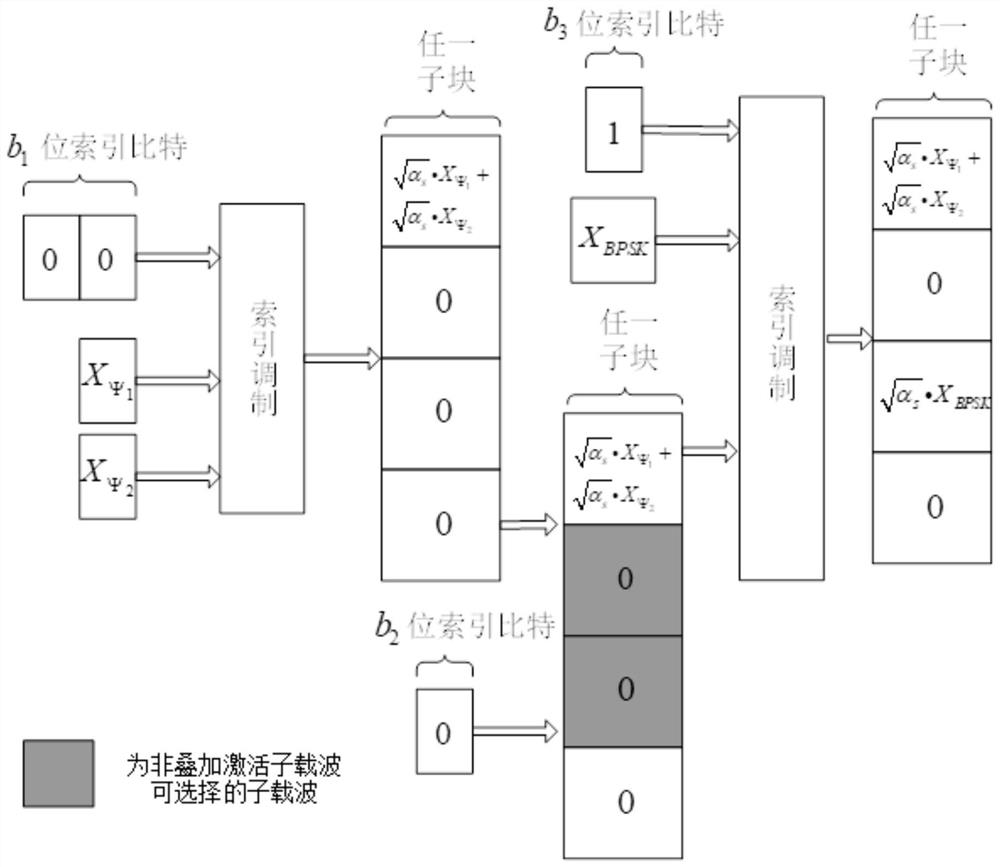
[0020] Assume that the SIM-OFDM system has N=1024 subcarriers, which are divided into G=N / n=256 sub-blocks, and each sub-block has n=4 sub-carriers. The system takes a sub-block as a unit, and performs bit mapping in sequence according to the sub-blocks. Each sub-block is independent of each other. An arbitrary sub-block is used as an example for illustration. The method comprises the steps of:

[0021] The transmitting end:

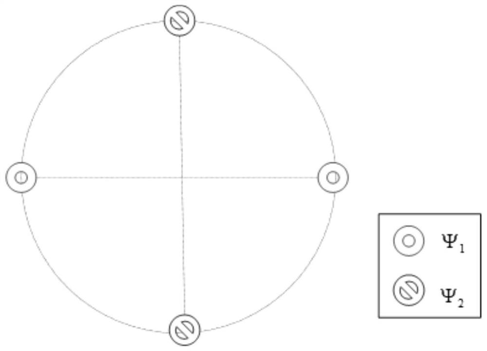
[0022] a. Power configuration: select k in each sub-block 1 = 1 superimposed active subcarrier, each superimposed activated subcarrier is superimposed and placed m 1 = 2 constellation point symbols, choose k 2 = 1 non-overlapping active subcarrier, and place 1 constellation point symbol on each non-overlapping active subcarrier, so a total of m=k is placed on the n subcarriers of the sub-block 1 m 1 +k 2 = 3 constellation point symbols, the normalized power allocated to each constellation point symbol is α s =n / m=4 / 3.

[0023] b. Select superimpo...


PUM


Abstract

The invention belongs to the technical field of wireless communication, and in particular relates to a multi-carrier waveform design method. In order to achieve a better balance between spectral efficiency and PAPR, the present invention proposes a multi-carrier waveform design scheme. Users superimpose multiple constellation point symbols on some activated subcarriers, and at the same time increase index bits through multiple indexing. In the same spectral efficiency When , the present invention only needs to activate a very small number of system sub-carriers to obtain a transmission waveform close to the low PAPR / CM value of a single-carrier signal.

Description

technical field [0001] The invention belongs to the technical field of wireless communication, and relates to a multi-carrier waveform design method, in particular to a single-carrier-like extremely low peak-to-average ratio multi-carrier waveform design method. Background technique [0002] The multi-carrier transmission technology represented by OFDM has the advantages of flexible configuration and simple operation, and is one of the mainstream air interface technologies of modern wireless communication. However, the multi-carrier waveform is likely to cause a relatively large peak-to-average power ratio. That is to say, its value at certain moments is relatively large, which will cause the power amplifier at the receiving end to enter a nonlinear state, which will cause nonlinear distortion of the OFDM signal, generate harmonics, and cause more obvious out-of-band spectrum spread interference and in-band The signal diffuses, and finally leads to the performance degradati...

Claims


Application Information

Patent Timeline
Patent Type & Authority Patents(China)
IPC IPC(8): H04L27/26
CPCH04L27/2602H04L27/2614
Inventor 但黎琳尤花征蒋婷敏
Owner UNIV OF ELECTRONICS SCI & TECH OF CHINA
Why Eureka
Try Eureka