High-efficiency energy-saving type cleaning device for producing mechanical equipment parts

A technology of mechanical equipment and cleaning devices, which is applied in the direction of using liquid cleaning methods, cleaning methods and utensils, chemical instruments and methods, etc., which can solve the impact of compression spring elastic performance, large space occupied by component structures, poor energy saving and environmental protection effects, etc. problems, to achieve the effect of reasonable structural layout, saving internal space and increasing vertical stability

Active Publication Date: 2019-04-16
义乌市思淇工业设计有限公司
View PDF9 Cites 6 Cited by
  • Summary
  • Abstract
  • Description
  • Claims
  • Application Information

AI Technical Summary

Problems solved by technology

[0004] The purpose of the present invention is to provide a cleaning device for the production of high-efficiency and energy-saving mechanical equipment parts, which can solve the problem that a large amount of energy needs to be consumed in the process of stirring the parts, the gravitational potential energy of the parts cannot be fully utilized, and the effect of energy saving and environmental protection is not good. Good, the structure of the internal parts of the device takes up a lot of space, which limits the amount of cleaning parts and reduces the cleaning rate, and the structural layout is unreasonable, and the elastic performance of the compression spring is easily affected due to excessive compression, shortening its service life.

Method used


Image

  • High-efficiency energy-saving type cleaning device for producing mechanical equipment parts
  • High-efficiency energy-saving type cleaning device for producing mechanical equipment parts
  • High-efficiency energy-saving type cleaning device for producing mechanical equipment parts

Examples


Embodiment Construction

[0035]The technical solutions of the present invention will be clearly and completely described below in conjunction with the embodiments. Apparently, the described embodiments are only some of the embodiments of the present invention, not all of them. Based on the embodiments of the present invention, all other embodiments obtained by persons of ordinary skill in the art without creative efforts fall within the protection scope of the present invention.

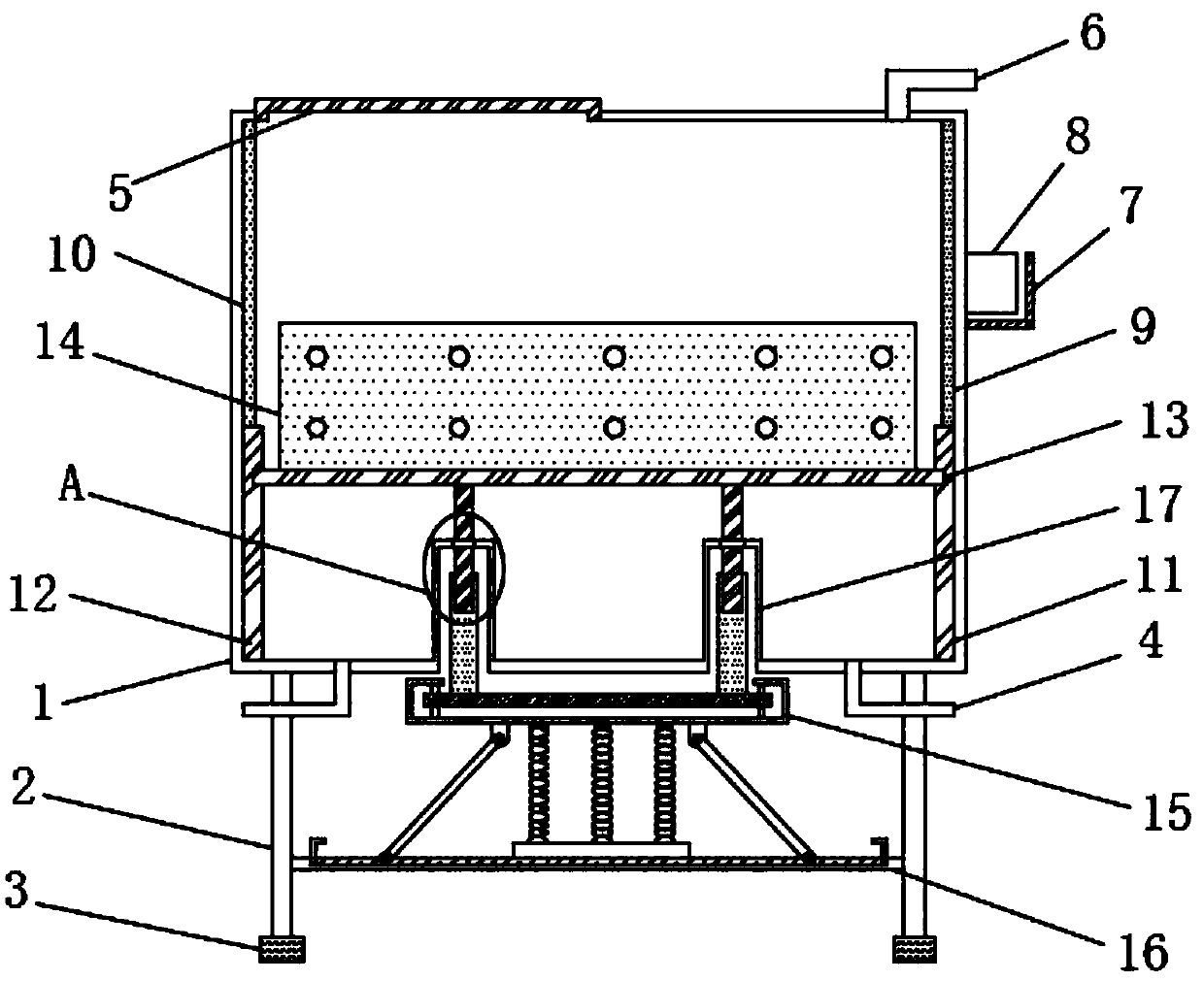
[0036] see figure 1 As shown, a cleaning device for the production of high-efficiency and energy-saving mechanical equipment parts includes a device main body 1, and a support frame 2 is fixedly installed on the corner of the bottom outer surface of the device main body 1, and the bottom of the support frame 2 The end surface is equipped with supporting feet 3, and the middle position of both sides of the bottom of the device main body 1 is provided with a water outlet 4. The upper end of the device main body 1 is movably in...


PUM


Abstract

The invention discloses a high-efficiency energy-saving type cleaning device for producing mechanical equipment parts. The high-efficiency energy-saving type cleaning device for producing the mechanical equipment parts comprises a device main body, wherein supporting frames are fixedly arranged at corner positions of the outer surface of the bottom end of the device main body, supporting legs arearranged on the bottom end surfaces of the supporting frames, water outlets are formed in the middle positions of both sides of the bottom end of the device main body, a cover plate is movably arranged at the upper end of the device main body, and a water inlet is formed in one side of the cover plate, and a supporting plate is fixedly arranged at the position, close to the upper end, of one sideof the device main body. According to the high-efficiency energy-saving type cleaning device for producing the mechanical equipment parts, the gravitational potential energy of the parts can be fullyutilized to realize energy conversion and transmission, energy saving and environment protection are achieved, the parts in the cleaning device are effectively agitated, cleaning of the parts is facilitated, the cleaning effect and cleaning efficiency of the parts are greatly improved, excessive compression of a compression spring is effectively prevented from affecting the elastic performance ofthe compression spring, the service life of the parts is prolonged, and reasonable structural layout is achieved.

Description

technical field [0001] The invention relates to a parts cleaning device, in particular to a cleaning device for the production of high-efficiency and energy-saving mechanical equipment parts. Background technique [0002] Laser cleaning The traditional cleaning industry has a variety of cleaning methods, most of which use chemical agents and mechanical methods for cleaning. Today, as my country's environmental protection laws and regulations are becoming more and more stringent, and people's awareness of environmental protection and safety is increasing, the types of chemicals that can be used in industrial production cleaning will become less and less. How to find a cleaner and non-destructive cleaning method is a problem we have to consider. Laser cleaning has the characteristics of non-grinding, non-contact, non-thermal effect and applicable to objects of various materials, and is considered to be the most reliable and effective solution. At the same time, laser cleanin...

Claims


Application Information

Patent Timeline
Patent Type & Authority Applications(China)
IPC IPC(8): B08B7/00B08B3/04B08B3/08B08B13/00
CPCB08B3/044B08B3/045B08B3/047B08B3/08B08B7/0042B08B13/00
Inventor 吴有军
Owner 义乌市思淇工业设计有限公司
Why Eureka
Try Eureka