
A fully automatic uncoiler with feeding and speed control functions

A fully automatic, uncoiler technology, used in manufacturing tools, metal processing equipment, metal processing, etc., can solve problems such as high cost and complex structure, and achieve the effect of convenient maintenance, convenient operation and cost reduction in the later period.

Active Publication Date: 2020-10-13
SICHUAN TIANHONG STAINLESS STEEL
View PDF6 Cites 0 Cited by
  • Summary
  • Abstract
  • Description
  • Claims
  • Application Information

AI Technical Summary

Problems solved by technology

It can be seen from its manual that the means of speed control is to control the uncoiling speed and tension, the structure is more complicated and the cost is higher

Method used


Image

  • A fully automatic uncoiler with feeding and speed control functions
  • A fully automatic uncoiler with feeding and speed control functions
  • A fully automatic uncoiler with feeding and speed control functions

Examples


Embodiment 1

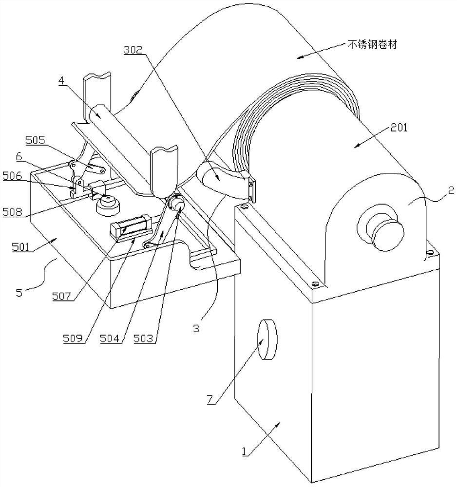
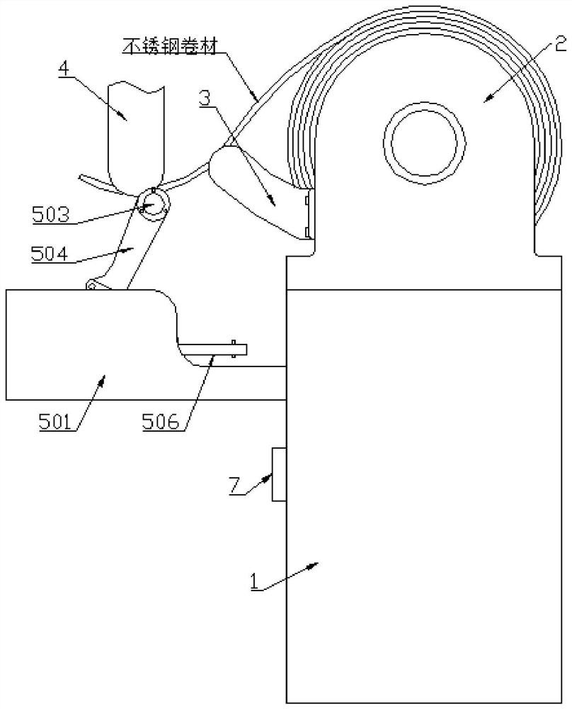
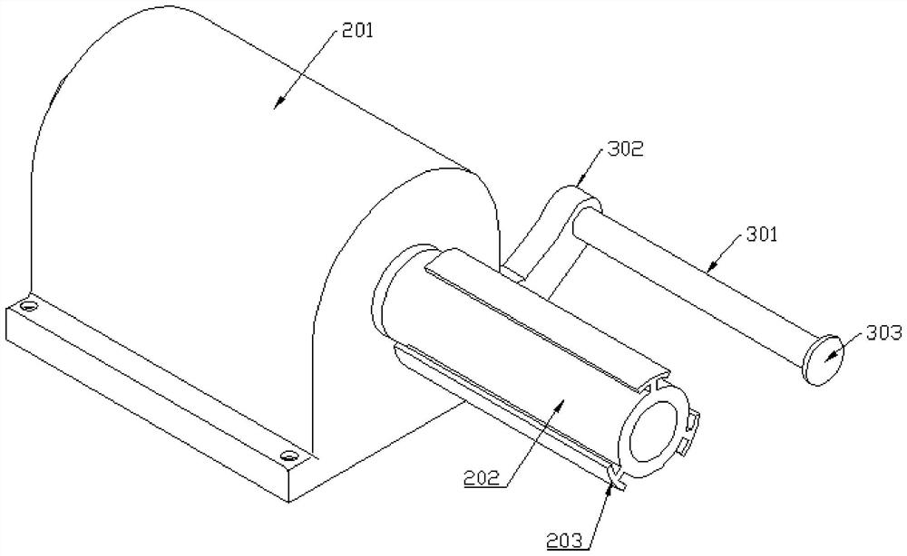
[0025] Such as Figure 1 to Figure 4 As shown, a fully automatic uncoiler with feeding and speed control functions, including a machine base 1, a power device 2, a support assembly 3, a tension roller 4, an ultrasonic sensor 6 and a speed control device 5, the power The device 2 is installed on the machine base 1, the support assembly 3 is installed on the side of the power device 2 and supports the stainless steel coil, and the tension roller 4 is located above the stainless steel coil and downstream of the support assembly 3 end (that is, the feeding direction of the stainless steel coil);

[0026] The speed control device 5 includes a tray 501, a speed control roller shaft 502, a servo motor 503, a side plate 504, a linkage plate 505, a guide rod 506 and a linear drive device 507, and the tray 501 is installed on the base 1 through an L-shaped bracket. and located below the tension roller 4, the speed control roller shaft 502 is rotatably connected between the two side pla...

Embodiment 2

[0032] as attached Figure 4 As shown, a fully automatic uncoiler with feeding and speed control functions, including a machine base 1, a power device 2, a support assembly 3, a tension roller 4, an ultrasonic sensor 6 and a speed control device 5, the power The device 2 is installed on the machine base 1, the support assembly 3 is installed on the side of the power device 2 and supports the stainless steel coil, and the tension roller 4 is located above the stainless steel coil and downstream of the support assembly 3 end (that is, the feeding direction of the stainless steel coil);

[0033] The speed control device 5 includes a tray 501, a speed control roller shaft 502, a servo motor 503, a side plate 504, a linkage plate 505, a guide rod 506 and a linear drive device 507, and the tray 501 is installed on the base 1 through an L-shaped bracket. and located below the tension roller 4, the speed control roller shaft 502 is rotatably connected between the two side plates 504 ...


PUM


Abstract

The invention discloses a fully-automatic uncoiling machine with feeding-in and speed-controlling functions, and relates to the technical field of stainless steel coil deep machining. The fully-automatic uncoiling machine comprises a machine seat, a power device, a material supporting assembly, a tensioning roller, an ultrasonic inductor and a speed controlling device, the power device is mountedon the machine seat, the material supporting assembly is mounted on the side face of the power device and supports a stainless steel coil, and the tensioning roller is located on the upper part of thestainless steel coil and located at the downstream end of the material supporting assembly. According to the fully-automatic uncoiling machine, height information at the lowest point of the coil is detected through the ultrasonic inductor and is fed back to a controller, when the height is low, the speed controlling device is started, the unwinding speed is controlled and limited to be a fixed numerical value, the speed controlling purpose can be achieved without changing the structure of the power device, the product structure is simplified, and the cost is lowered.

Description

technical field [0001] The invention relates to the technical field of deep processing of stainless steel coils, in particular to a fully automatic uncoiler with feeding and speed control functions. Background technique [0002] The strip steel coil is a strip steel state formed by coiling continuous steel strips, which is convenient for storage and transportation. It can reduce storage and transportation space, reduce storage and transportation costs, and is conducive to the normal use of strip steel. . An uncoiler is a device that unrolls a cylindrical steel coil continuously or intermittently. At present, there are many forms of uncoilers. In terms of functions, there are mainly mechanical passive uncoilers, semi-automatic uncoilers, and fully automatic uncoilers. [0003] The fully automatic uncoiler in the current fully automated production line can automatically feed the steel coil into the production line, and the steel plate uncoiled from the uncoiler is suspended ...

Claims


Application Information

Patent Timeline
Patent Type & Authority Patents(China)
IPC IPC(8): B21C47/18B21C47/34B21C51/00
CPCB21C47/18B21C47/34B21C51/00
Inventor 瞿坤马继亭
Owner SICHUAN TIANHONG STAINLESS STEEL
Learn More