
A zero position device and zero return method for a mechanical arm joint

A technology of mechanical arms and joints, which is applied in the field of robot rotary joint design, can solve problems such as interference and collision, and achieve the effects of saving change time, high repeat positioning accuracy, and reducing power-on initialization time

Active Publication Date: 2021-02-09
BEIJING RES INST OF PRECISE MECHATRONICS CONTROLS
View PDF6 Cites 0 Cited by
  • Summary
  • Abstract
  • Description
  • Claims
  • Application Information

AI Technical Summary

Problems solved by technology

Rotate in a fixed direction after power-on, which may cause interference collision

Method used


Image

  • A zero position device and zero return method for a mechanical arm joint
  • A zero position device and zero return method for a mechanical arm joint

Examples


Embodiment Construction

[0030] Below in conjunction with accompanying drawing and specific embodiment the present invention is described in further detail:

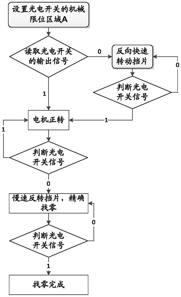
[0031] The invention provides a mechanical arm joint zero position device and a zero return method. The motion controller sends a motion command to the motor driver. Rotate, when the photoelectric switch 1 detects the zero position signal, it feeds back the position signal to the motion controller, and the motion controller obtains the absolute position information of the joint, and the robot joint zero return task is completed.

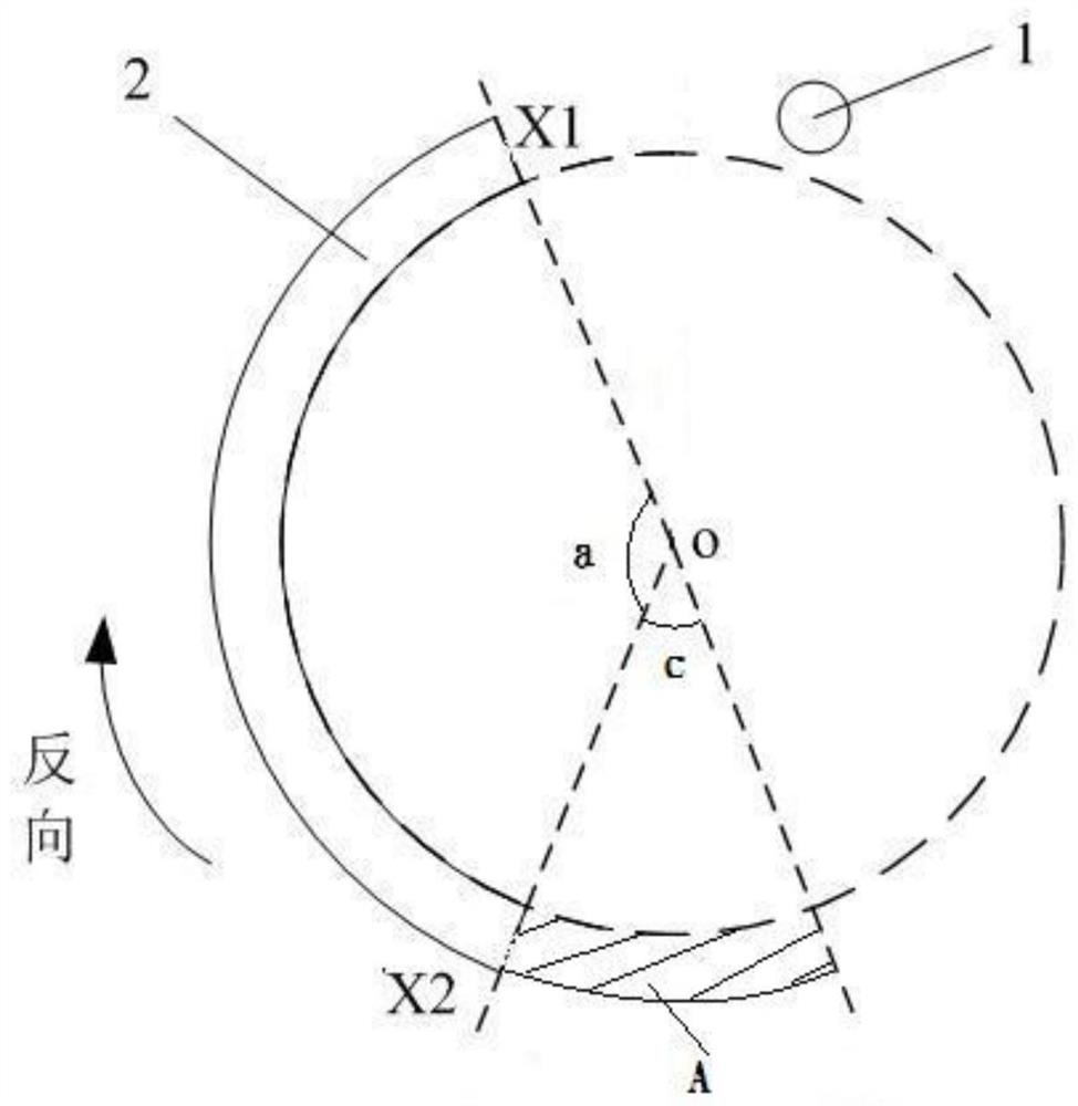
[0032] Such as figure 1 Shown is a schematic diagram of the zero position device of the mechanical arm joint. It can be seen from the figure that a kind of mechanical arm joint zero position device includes a photoelectric switch 1 and a stopper 2; wherein the stopper 2 is an arc-shaped sheet structure; the stopper 2 is o The point is the center of the circle for circular rotation; the photoelectric switch 1 is fixed ...


PUM


Abstract

A zero position device and a zero return method for a mechanical arm joint, relating to the field of robot rotary joint design; including a photoelectric switch and a block; wherein, the block is an arc-shaped sheet structure; the block rotates in a circle with point o as the center; the photoelectric The switch is fixed on the circular rotation path of the stopper; when the stopper rotates to the position where the photoelectric switch is blocked, the output signal of the photoelectric switch is 1; when the stopper rotates to the position where the photoelectric switch is not blocked, the output signal of the photoelectric switch is 0 The center angle a of the baffle plate corresponding to the center o point is 60°-200°; the present invention adopts a simple photoelectric switch as the sensor of the zero return scheme, and the scheme is simple and has high reliability; meanwhile, the present invention can know The general area where the joints of the manipulator are currently located can be interpreted in which direction the joints should go for change, which greatly saves the time for change and reduces the time for power-on and initialization of the manipulator.

Description

technical field [0001] The invention relates to the design field of a rotary joint of a robot, in particular to a zero position device and a zero return method for a mechanical arm joint. Background technique [0002] The robot joint is the basic component of the robot, and its performance directly affects the performance of the robot. There are many types of robot joints. According to the different functions of the robot, the configuration of the joints and the form of the motion system are also different. [0003] The common joint forms of robots are mobile joints and rotational joints. The most widely used robot is a multi-joint robot, which is mainly composed of multiple rotary joints and connecting rods, simulating the functions of human shoulder joints, elbow joints and wrist joints. [0004] For the robot, the robot controller will lose the position information of each joint after the power is turned on again, or the position of some joints of the robot will change ...

Claims


Application Information

Patent Timeline
Patent Type & Authority Patents(China)
IPC IPC(8): B25J13/08B25J9/16
CPCB25J9/1628B25J13/088
Inventor 程远超王昊蔡赫李科王燕波
Owner BEIJING RES INST OF PRECISE MECHATRONICS CONTROLS
Learn More