Automatic transferring and placing equipment for building floor slabs and working method thereof

A floor and equipment technology, applied in the field of transfer and placement equipment, can solve the problems of inability to flexibly adjust the position and angle of the floor, time-consuming and laborious, and low adaptability, so as to expand the range of movable transfer, facilitate operation, and ensure portability Effect

Active Publication Date: 2019-04-16
云南天珲建设工程有限公司
View PDF8 Cites 7 Cited by
  • Summary
  • Abstract
  • Description
  • Claims
  • Application Information

AI Technical Summary

Problems solved by technology

[0004] The purpose of the present invention is to solve the problem that the existing transfer and placement equipment for building floors is time-consuming and laborious to use, and the automation degree of work is low, the efficiency of transferring and placing the building floors is slow, and the process of transferring the building floors is difficult. , cannot flexibly adjust the position and angle of the floor when it is moving, and the stability of the floor during the transfer process is poor, and it is easy to shake and cause the floor to fall, and the transfer and placement equipment can only transfer and place floors of the same width and size, which is suitable In order to solve the problem of low compatibility, an automatic transfer and placement equipment for building floors and its working method are proposed

Method used


Image

  • Automatic transferring and placing equipment for building floor slabs and working method thereof
  • Automatic transferring and placing equipment for building floor slabs and working method thereof
  • Automatic transferring and placing equipment for building floor slabs and working method thereof

Examples


Embodiment Construction

[0038] The technical solutions of the present invention will be clearly and completely described below in conjunction with the embodiments. Apparently, the described embodiments are only some of the embodiments of the present invention, not all of them. Based on the embodiments of the present invention, all other embodiments obtained by persons of ordinary skill in the art without creative efforts fall within the protection scope of the present invention.

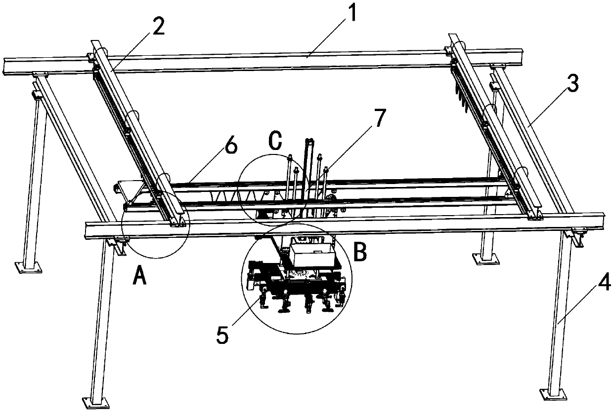
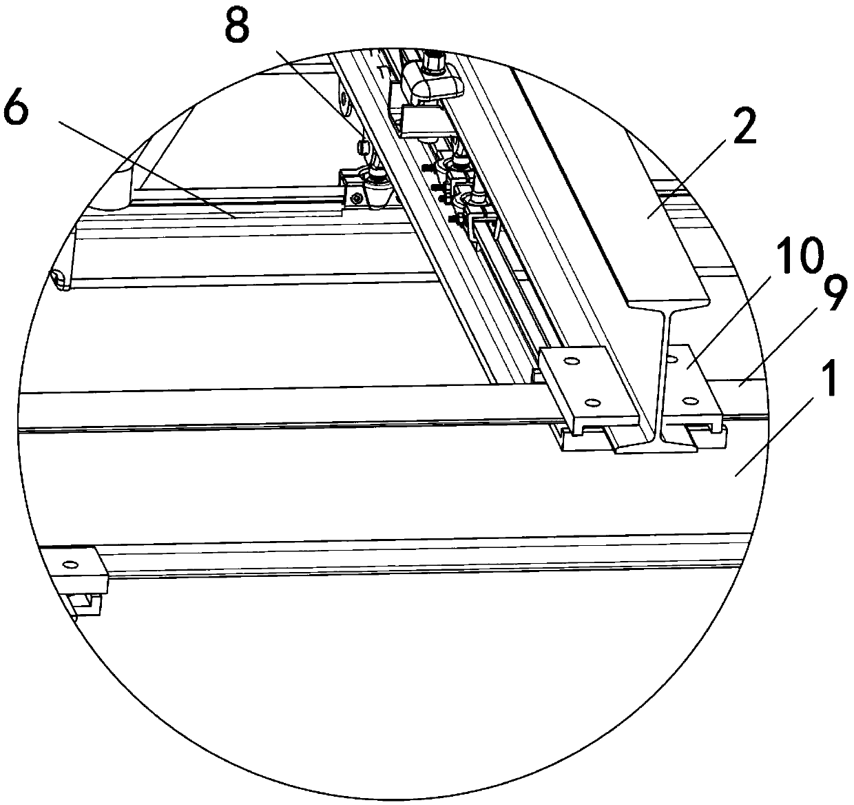
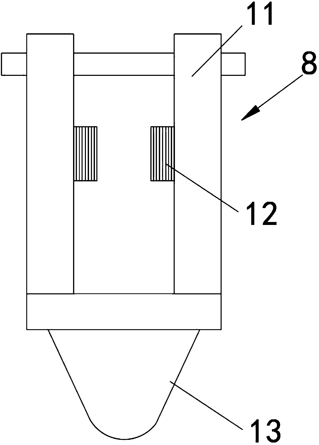
[0039] see Figure 1-8 As shown, an automatic transfer and placement equipment for building floors includes two upper struts 1, two traversing rods 2, a grabbing plate 5 and two longitudinal shifting rods 6, and the two upper struts 1 are respectively set At both ends of the top of the equipment, and both ends of the two upper support rods 1 are vertically installed with traversing rods 2, side support rods 3 are arranged in parallel under one side of the two traversing rods 2, and the bottom of the traversing rod 2 Two lo...


PUM


Abstract

The invention discloses an automatic transferring and placing equipment for building floor slabs and a working method thereof. The automatic transferring and placing equipment comprises two upper supporting rods, two transverse moving rods, a grabbing disc and two longitudinal moving rods, the two upper supporting rods are arranged at the two ends of the top of the equipment respectively, and thetwo ends of the two upper supporting rods are respectively and vertically provided with transverse moving rods, side supporting rods are arranged below one sides of the two transverse moving rods in parallel. The equipment has the beneficial effects that the grabbing disc is connected with a motor V through a connecting plate at the top, the motor V drives the rolling wheels IV at the two ends toroll in clamping grooves of the longitudinal moving rods, so that the floor slabs at the bottom of the grabbing disc are driven to move left and right, and a motor I on a moving seat I rolls on connecting rods at the bottom of the transverse moving rods through rolling wheels I, so that the longitudinal moving rods and the grabbing disc can be driven to move forwards and backwards, and the equipment is guaranteed to drive the floor slabs to carry out adjustment and movement transferring forwards, backwards, leftwards and rightwards, and the floor slabs can be conveniently grabbed and transferred to a designated position, so that a worker can conveniently use and operate the floor slabs, and the portability of use is guaranteed.

Description

technical field [0001] The invention relates to a transfer and placement device, in particular to an automatic transfer and placement device for building floors and a working method thereof, belonging to the technical field of transfer and placement equipment application. Background technique [0002] The building floor is indispensable in the building construction process. When building the building floor, the staff needs to transfer and place the equipment to move the floor to the designated location, reduce the occupied space of the floor, and facilitate the staff to lift the floor for construction use. [0003] The existing transfer and placement equipment for building floors still has many deficiencies in use. The existing transfer and placement equipment for building floors is time-consuming and laborious to use, and the degree of automation of the work is low. The efficiency of transfer placement is slow, and during the transfer process of the building floor, the pos...

Claims


Application Information

Patent Timeline
Patent Type & Authority Applications(China)
IPC IPC(8): B65G47/90
CPCB65G47/901
Inventor 徐勇
Owner 云南天珲建设工程有限公司
Why Eureka
Try Eureka