A yarn splitting device

A technology of yarn separation and thread separation, which is applied to textiles and papermaking, etc., can solve the problems of easy yarn knotting, simple structure and easy thread breakage, etc., and achieve the effects of high yarn separation efficiency, simple structure and convenient operation.

Active Publication Date: 2021-11-09
LINZHOU GUANGYUAN NEW MATERIAL TECH
View PDF5 Cites 0 Cited by
  • Summary
  • Abstract
  • Description
  • Claims
  • Application Information

AI Technical Summary

Problems solved by technology

[0002] In the current textile industry, the yarn needs to be separated by a yarn splitting device, then arranged together in turn, and re-twisted together, that is, after the yarn is twisted, it can be spun. However, in the process of yarn splitting Among them, the existing yarn splitting device has a simple structure, the yarn bundles are easy to twist together during yarn splitting, the yarn is easy to knot, the efficiency is low, and the situation of thread breakage is easy to occur, the quality of the yarn splitting is poor, and it is not convenient to use

Method used


Image

  • A yarn splitting device
  • A yarn splitting device
  • A yarn splitting device

Examples


Embodiment 1

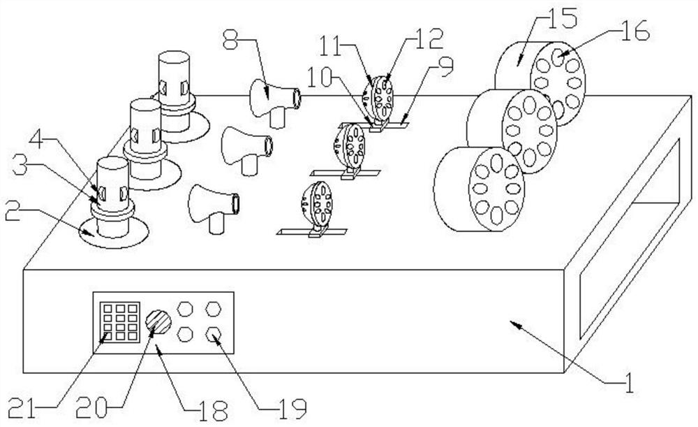
[0025] Such as Figure 1-4 As shown, a yarn splitting device includes a workbench 1, a pay-off shaft 3, a servo motor 5, a wire horn 8, and a photoelectric switch 17. A row of several turntables 2 are installed on the workbench 1, and each turntable 2 is A pay-off shaft 3 is welded, and four blocks 4 are installed on the pay-off shaft 3. A row of wire horns 8, a row of branching heads 11, and a row of wire drums 15 are successively arranged on one side of a row of turntables 2. The wire horns The cylinder 8 is welded on the workbench 1 through the support rod, the branch wire 11 is welded on the slider 10 through the support rod, the slider 10 is installed in the chute 9 set on the workbench 1, and the wire barrel 15 is welded on the workbench 1 .

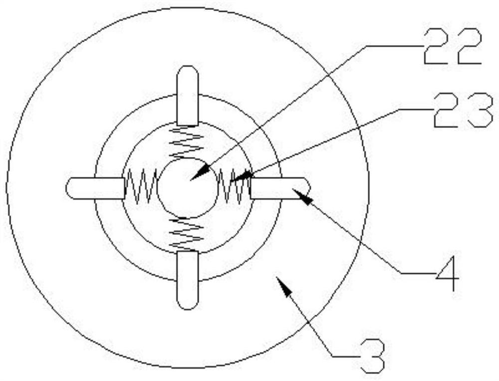
[0026] Each pay-off shaft 3 is provided with a vertical rod 22, and the four blocks 4 are connected to the vertical rod 22 by connecting springs 23. The elastic force makes the clamping block 4 be pressed outwards, thereby blocki...

Embodiment 2

[0030] Such as Figure 1-4 As shown, the wire trumpet 8 is a horn-shaped wire barrel, and its horn-shaped opening is facing the pay-off shaft 3, and the branching head 11 is a lotus-shaped cylinder with one side protruding, and its protruding side is facing To wire trumpet 8, several branch holes 12 are arranged on branch head 11, and several wire holes 16 are correspondingly arranged on wire barrel 15, and photoelectric switch 17 is all inlaid in the inner wall of each wire hole 16.

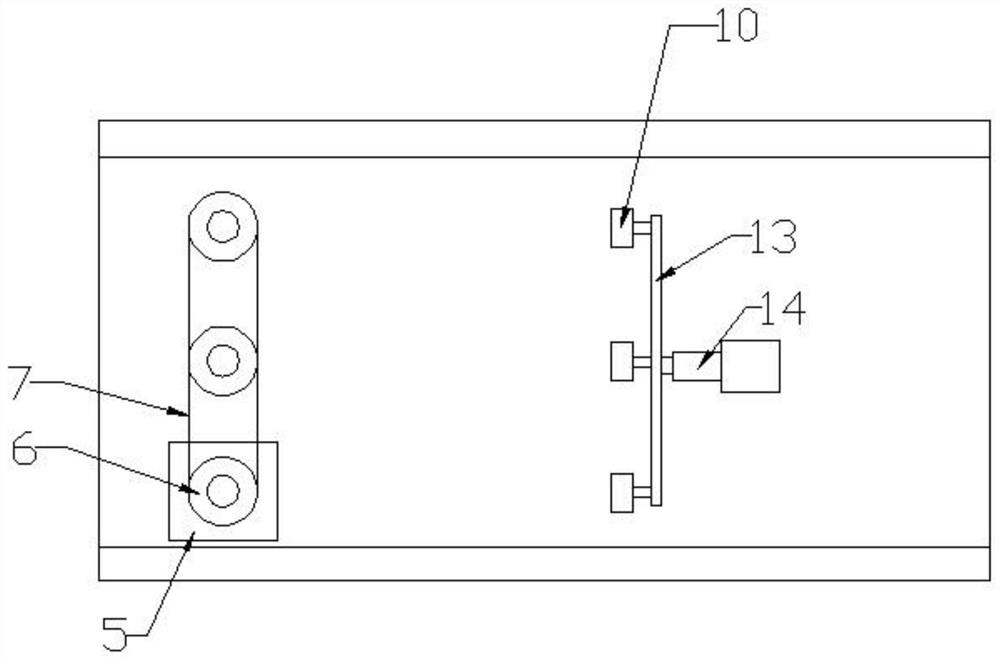
[0031] Several sliders 10 are all connected to the same connecting rod 13, the bottom end of the workbench 1 is equipped with an electric push rod 14 through bolts, and the connecting rod 13 is installed on the piston end of the electric push rod 14 through bolts. Telescoping drives the slider 10 to move back and forth in the chute 9, and then makes the branching head 11 close to or away from the wire horn 8.

[0032] One side of workbench 1 is equipped with control box 18, and control box 18 c...


PUM


Abstract

A yarn splitting device, including a workbench, a pay-off shaft, a servo motor, a wire horn and a photoelectric switch, a row of several turntables are installed on the workbench, each turntable is welded with a pay-off shaft, and the pay-off shaft is installed There are four blocks. One side of a row of turntables is provided with a row of wire horns, a row of branch wires and a row of wire barrels. The wire horns are welded on the workbench through the support rod, and the branch wires are welded on the slide through the support rod. On the block, the slider is installed in the chute set on the workbench, and the wire barrel is welded on the workbench; the invention discloses that the yarn splitting device of the invention drives the lotus-shaped thread splitter to move back and forth through the electric push rod and the slider, Make the yarn splitting head back and forth to disperse the yarn bundle, so that each yarn is separated through the thread splitting hole, and the thread splitting head moves back and forth, which can give the yarn a buffer force, so that the yarn bundle is divided under the push of the thread splitting head, and No knotting, no yarn breakage, high yarn splitting efficiency.

Description

technical field [0001] The invention relates to the technical field of textile equipment, in particular to a yarn dividing device. Background technique [0002] In the current textile industry, the yarn needs to be separated by a yarn splitting device, then arranged together in turn, and re-twisted together, that is, after the yarn is twisted, it can be spun. However, in the process of yarn splitting Among them, the existing yarn splitting device has a simple structure, the yarn bundles of the yarn are easily twisted together during yarn splitting, the yarn is easy to knot, the efficiency is low, and the situation of thread breakage is prone to occur, the quality of the yarn split is poor, and it is not convenient to use. Contents of the invention [0003] The purpose of the present invention is to solve the problems in the prior art, and propose a yarn splitting device. [0004] In order to achieve the above object, the present invention adopts the following technical so...

Claims


Application Information

Patent Timeline
Patent Type & Authority Patents(China)
IPC IPC(8): D02J1/18
CPCD02J1/18
Inventor 宁祥春李伟
Owner LINZHOU GUANGYUAN NEW MATERIAL TECH
Why Eureka
Try Eureka