A pay-off device for surveying and mapping
The technology of a pay-off device and a wire reel is applied in the field of surveying and mapping pay-off, which can solve the problems of easy knotting, inconvenient retracting and laying of surveying and mapping lines, and breakage of surveying and mapping lines, and achieves the effects of reducing wear, convenient marking, and convenient connection.
- Summary
- Abstract
- Description
- Claims
- Application Information
AI Technical Summary
Problems solved by technology
Method used
Image
Examples
Embodiment 1
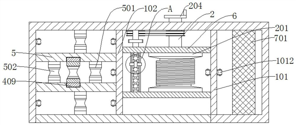
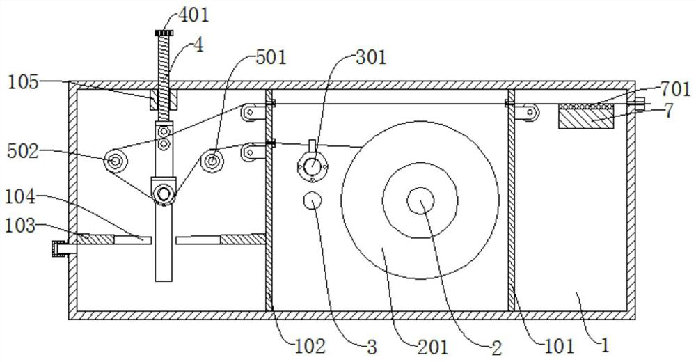
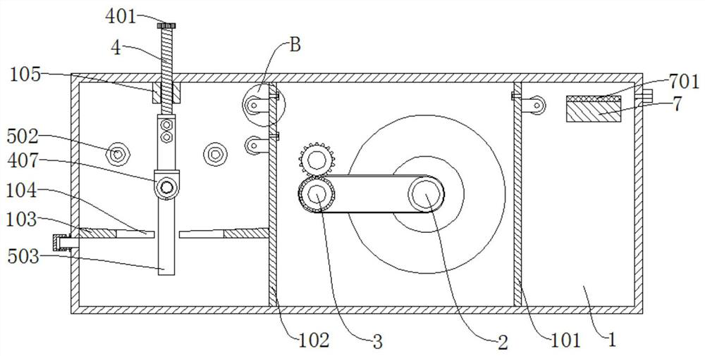
[0035] refer to Figure 1-7 , a pay-off device for surveying and mapping, comprising a box body 1, the inner wall of the box body 1 is fixedly connected with a first baffle plate 101 and a second baffle plate 102, respectively, between the first baffle plate 101 and the second baffle plate 102 The first rotating shaft 2, the second rotating shaft 3 and the reciprocating screw rod 301 are connected in rotation;
[0036] The outer wall of the first rotating shaft 2 is connected with a winding disk 201, and the outer wall of the reciprocating screw rod 301 is connected with an auxiliary winding member;
[0037] A first fixed plate 402 is also slidably connected between the second baffle plate 102 and the side wall of the box body 1, the bottom of the first fixed plate 402 is connected with a first connecting plate 403, and the outer walls of the first connecting plate 403 are respectively connected with A first pulley 404 and a second pulley 405 cooperating with each other;
[...
Embodiment 2
[0049] refer to Figure 1-7 , a pay-off device for surveying and mapping, comprising a box body 1, the inner wall of the box body 1 is fixedly connected with a first baffle plate 101 and a second baffle plate 102, respectively, between the first baffle plate 101 and the second baffle plate 102 The first rotating shaft 2, the second rotating shaft 3 and the reciprocating screw rod 301 are connected in rotation;
[0050] The outer wall of the first rotating shaft 2 is connected with a winding disk 201, and the outer wall of the reciprocating screw rod 301 is connected with an auxiliary winding member;
[0051] A first fixed plate 402 is also slidably connected between the second baffle plate 102 and the side wall of the box body 1, the bottom of the first fixed plate 402 is connected with a first connecting plate 403, and the outer walls of the first connecting plate 403 are respectively connected with A first pulley 404 and a second pulley 405 cooperating with each other;
[...
Embodiment 3
[0064] On the basis of embodiment 1 or embodiment 2, such as Figure 8 with Figure 9 As shown, this embodiment also includes two wearers, the two wearers are arranged at the position of the outlet hole, and the two wearers are symmetrically arranged on the upper and lower sides of the marking line, and the wearers include return springs 801, reset Rod 802 and wear-resistant roller 803. The hardness of wear-resistant roller 803 is less than or equal to the hardness of the marking line. Since the marking line is wound on the winding reel 201, it is inconvenient to replace and the replacement cost is high. When the hardness of the marking line is less than that of the wear-resistant roller When the hardness is 803, the marking line wears before the wear-resistant roller 803, which causes the marking line to be easily worn and broken, but when the hardness of the wear-resistant roller 803 is less than the hardness of the marking line, the wear-resistant roller 803 wears first, th...
PUM
 Abstract
Description
Claims
Application Information
 - R&D
- Intellectual Property
- Life Sciences
- Materials
- Tech Scout
- Unparalleled Data Quality
- Higher Quality Content
- 60% Fewer Hallucinations
Browse by: Latest US Patents, China's latest patents, Technical Efficacy Thesaurus, Application Domain, Technology Topic, Popular Technical Reports.
© 2025 PatSnap. All rights reserved.Legal|Privacy policy|Modern Slavery Act Transparency Statement|Sitemap|About US| Contact US: help@patsnap.com


