Construction expansion and contraction device and method for viaduct bridge

A telescopic device, viaduct technology, applied in measuring devices, optical devices, bridges, etc., can solve the problems of lack of reliable data, repair, bridge damage, etc., and achieve the effect of firm and reliable structure, simple and convenient installation, and avoiding danger.

Inactive Publication Date: 2019-04-16
洛阳城市建设勘察设计院有限公司
View PDF7 Cites 0 Cited by
  • Summary
  • Abstract
  • Description
  • Claims
  • Application Information

AI Technical Summary

Problems solved by technology

[0004] (1) The existing viaduct construction expansion device cannot measure the size of the expansion joint, resulting in no reliable data as a reference for maintenance of the bridge, causing serious damage to the bridge
[0005] (2) In the existing telescopic device for viaduct construction, when the weld seam increases, larger fragments fall into the expansion joint, reducing the use effect of the telescopic device
[0006] (3) In the prior art, the expansion joints in the viaduct construction expansion device cannot be detected in real time, so that if there is a sudden change in the viaduct, measures cannot be taken to repair the bridge, so that danger will occur at any time

Method used


Image

  • Construction expansion and contraction device and method for viaduct bridge
  • Construction expansion and contraction device and method for viaduct bridge
  • Construction expansion and contraction device and method for viaduct bridge

Examples


Embodiment Construction

[0033] In order to further understand the invention content, characteristics and effects of the present invention, the following examples are exemplified and described in detail in conjunction with the accompanying drawings as follows.

[0034] The structure of the present invention will be described in detail below in conjunction with the accompanying drawings.

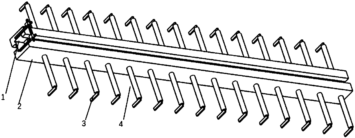
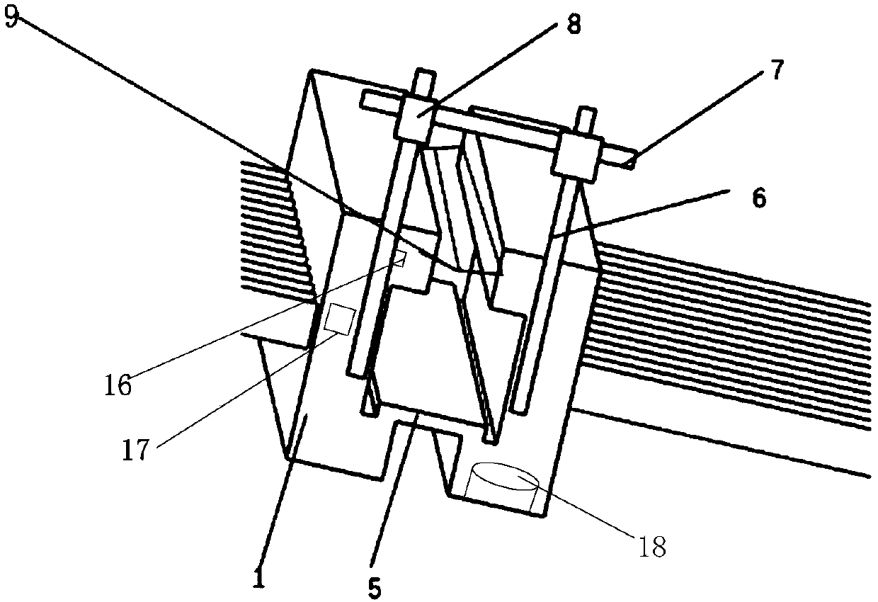
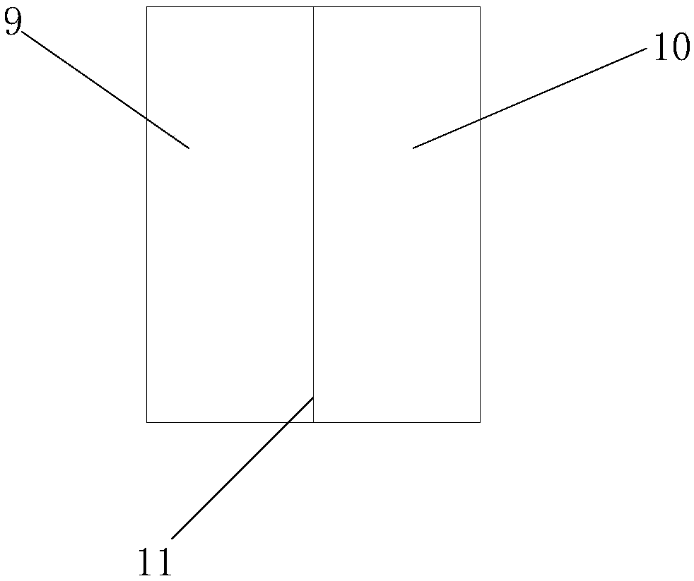
[0035] Such as Figure 1-Figure 9 As shown, the telescopic device for viaduct construction provided by the embodiment of the present invention includes: expansion joint 1, main frame 2, fixing claw 3, anchoring steel bar 4, connecting block 5, fixing frame 6, measuring ruler 7, ferrule 8, rubber pad 9 , the first rubber pad 10, the second rubber pad 11, the T-shaped groove 12, the main frame end 13, the main rod 14, the wings 15, the laser distance sensor 16, the control box 17, the solar panel support rod fixing groove 18.

[0036] The main frame 2 is welded with anchoring steel bars 4, and the anchoring steel bars...


PUM


Abstract

The invention belongs to the technical field of road construction equipment and discloses a construction expansion and contraction device and method for a viaduct bridge. The device is provided with amain rack; the main rack is provided with a main rack end, a fixing rack is fixedly welded to the main rack end, a clamping sleeve is fixed to a fixing rack, and a measurement ruler sleeves the clamping sleeve; anchoring rebars are welded to the main rack, and spiral wings are in melting connection with the anchoring rebars; an expansion and contraction joint is formed in the middle of the main rack; fixing claws are welded to the ends of the anchoring rebars, the anchoring rebars are provided with main rods, and wings are welded to the main rods; a rubber pad is clamped to the main rack, therubber pad is provided with a first rubber pad body and a second rubber pad body, and the first rubber pad body is connected to the second rubber pad through a connection buckle. According to the device, by arranging the measurement ruler, thermal expansion and cold contraction variation can be measured, and the expansion and contraction magnitude can be estimated; by arranging the rubber pad, afragment is prevented from entering the expansion and contraction joint through points, and the application effect of the expansion and contraction device is lowered. According to the device, by arranging the fixing claws and the wings, the main rack can be prevented from moving.

Description

technical field [0001] The invention belongs to the field of road construction, and in particular relates to a telescoping device method for viaduct construction. Background technique [0002] Construction expansion joints are expansion joints, which refer to a structural joint set at an appropriate part along the construction joint direction of a building or structure in order to prevent cracks or damage to the structure due to climate temperature changes (thermal expansion, cold contraction). The building or structure can be stretched horizontally along the long direction. Reserve gaps at certain distances along the length of the building to disconnect all the ground components of the building. The foundation of the building does not need to be disconnected because it is buried underground and is less affected by temperature changes. It is very important to reasonably select the gap with the proper amount of expansion and contraction. The larger the gap, the easier it is ...

Claims


Application Information

Patent Timeline
IPC IPC(8): E01D19/06G01B5/14G01B11/14
CPCE01D19/06G01B5/14G01B11/14
Inventor 胡斌郭遂军田昌林吕一品白飞飞李珂任维李华赵骁王宏伟褚彤王建钦邢俊峰程丽倩晋克强
Owner 洛阳城市建设勘察设计院有限公司
Why Eureka
Try Eureka