Cantilever support and construction method of concrete flange of steel-concrete composite bridge using cantilever support

A cantilever support and concrete technology, applied in the erection/assembly of bridges, bridges, bridge construction, etc., can solve the problems of slow construction speed, structural damage, affecting the appearance of the structure, etc., and achieve small bolting workload, small impact, and force transmission. clear path effect

Active Publication Date: 2020-04-10
TSINGHUA UNIV
View PDF4 Cites 1 Cited by
  • Summary
  • Abstract
  • Description
  • Claims
  • Application Information

AI Technical Summary

Problems solved by technology

[0004] However, for the cantilever flange part of the concrete bridge deck, the method of cantilever support formwork is still required in the pouring, and the installation of the cantilever support is mostly welded, and the bolts and connecting plates need to be cut during disassembly, which is easy to cause damage to the structure. Affects the beautiful structure and slow construction speed

Method used


Image

  • Cantilever support and construction method of concrete flange of steel-concrete composite bridge using cantilever support
  • Cantilever support and construction method of concrete flange of steel-concrete composite bridge using cantilever support
  • Cantilever support and construction method of concrete flange of steel-concrete composite bridge using cantilever support

Examples


Embodiment Construction

[0035] In order to make the technical solutions and advantages of the present invention clearer, the present invention will be further described in detail below in conjunction with the accompanying drawings and specific embodiments.

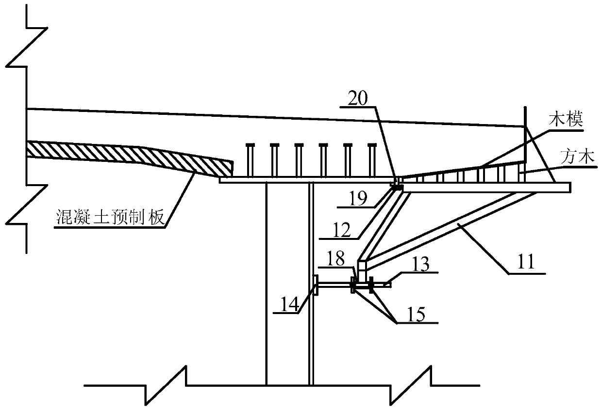
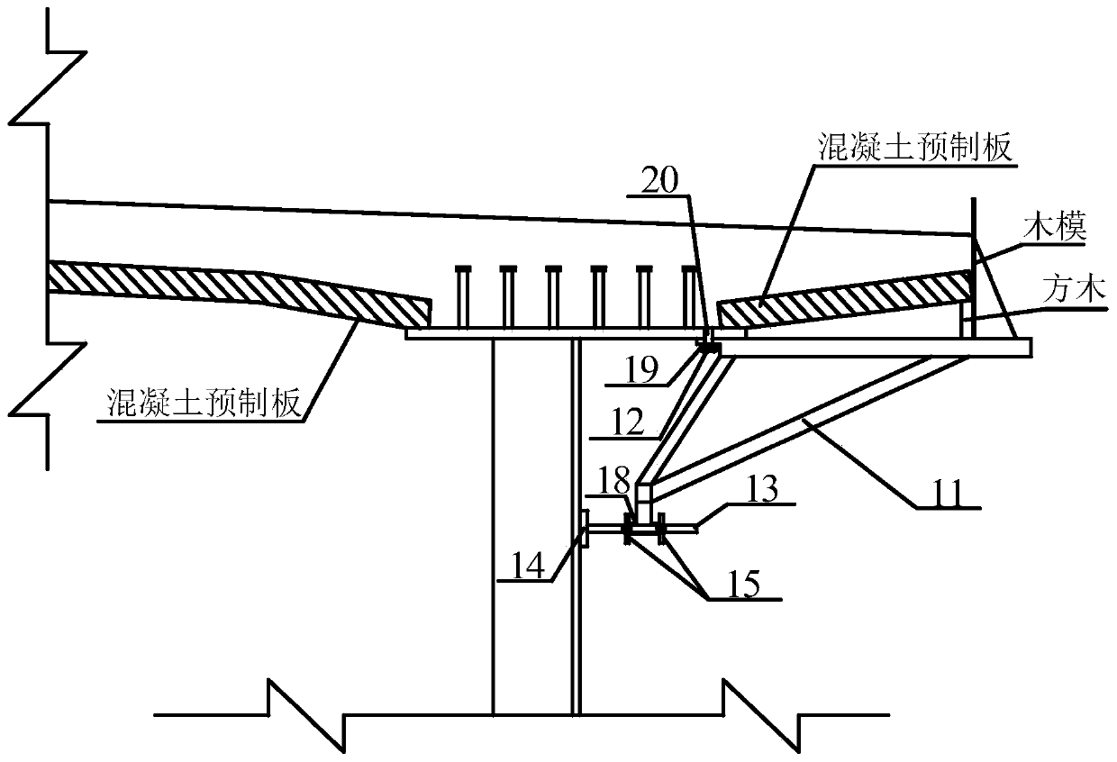
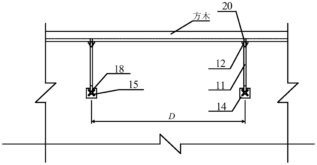
[0036] like Figure 1 to Figure 5 As shown, the detachable cantilever bracket used for the construction of the concrete flange of the steel-concrete composite bridge in the embodiment of the present invention includes: steel bracket 11, bolt 12, round steel rod 13, steel backing plate 14 and rotation limiting device 15 ;

[0037] The shape of the steel bracket 11 is an obtuse triangle; the obtuse end of the steel bracket 11 is provided with a connecting plate 16; the connecting plate 16 is provided with a bolt hole 17 for the passage of the bolt 12;

[0038] An acute angle end of the steel bracket 11 is provided with a steel sleeve 18;

[0039] One end of the round steel rod 13 is fixedly connected to the steel backing plate 14; the steel backi...


PUM


Abstract

The invention provides a detachable cantilever bracket and a construction method of steel-concrete composite bridge concrete flange using thereof. The cantilever bracket comprises a steel bracket, a bolt, a round steel rod, a steel backing plate and a rotation limiting device; the shape of the steel bracket is an obtuse angle triangle, and the obtuse angle end of the steel bracket is provided witha connecting plate; the acute angle end is provided with a steel sleeve; one end of the round steel rod is fixedly connected with the steel backing plate, and the other end of the round steel rod penetrates through the steel sleeve; the steel backing plate is in contact with the steel beam web plate; the rotary limiting device comprises a first limiter and a second limiter; internal threads corresponding to the external threads on the round steel rod are arranged in the first limiter and the second limiter. The first limiter and the second limiter are sleeving on the round steel rod through external threads and internal threads and are respectively positioned at two ends of the steel sleeve, and the steel sleeve is fixed on the round steel rod. The cantilever bracket and the constructionmethod of steel-concrete composite bridge concrete flange using thereof can realize the rapid installation and disassembly of the cantilever bracket, improve the construction speed, save the use costand have no damage to the structure.

Description

technical field [0001] The present application relates to the technical field of building structures, in particular to a cantilever support used for the construction of a concrete flange of a steel-concrete composite bridge and a construction method for the concrete flange of a steel-concrete composite bridge using the cantilever support. Background technique [0002] The steel-concrete composite bridge refers to the bridge structure that connects the steel girder and the concrete bridge deck through shear connectors and considers the joint force. Compared with steel structure bridges, composite bridges have the advantages of small steel consumption, high rigidity, and good compression stability. Compared with concrete bridges, composite bridges have the advantages of low structural height, low dead weight, large applicable span, and high ductility. In addition, the composite girder bridge adopts reasonable manufacturing and construction procedures, which is convenient for f...

Claims


Application Information

Patent Timeline
Patent Type & Authority Patents(China)
IPC IPC(8): E01D21/00E01D21/10
CPCE01D21/00E01D21/10
Inventor 聂鑫郭宇韬樊健生陶慕轩
Owner TSINGHUA UNIV
Why Eureka
Try Eureka