A Parameter Determination Method of Multi-channel Variable Wavelength Polarization Interference Filter

An interference filter and parameter determination technology, applied in the field of optical devices, can solve the problems of inability to continuously frequency modulation, long wavelength switching time, single channel, etc., and achieve the effect of small birefringence, strong environmental adaptability, and large optical aperture

Active Publication Date: 2021-02-19
深圳市合飞科技有限公司
View PDF5 Cites 0 Cited by
  • Summary
  • Abstract
  • Description
  • Claims
  • Application Information

AI Technical Summary

Problems solved by technology

[0006] The object of the present invention is to propose a method for determining the parameters of a multi-channel variable wavelength polarization interference filter, which can provide Multi-channel, wavelength continuously adjustable polarized light

Method used


Image

  • A Parameter Determination Method of Multi-channel Variable Wavelength Polarization Interference Filter
  • A Parameter Determination Method of Multi-channel Variable Wavelength Polarization Interference Filter
  • A Parameter Determination Method of Multi-channel Variable Wavelength Polarization Interference Filter

Examples


Embodiment 1

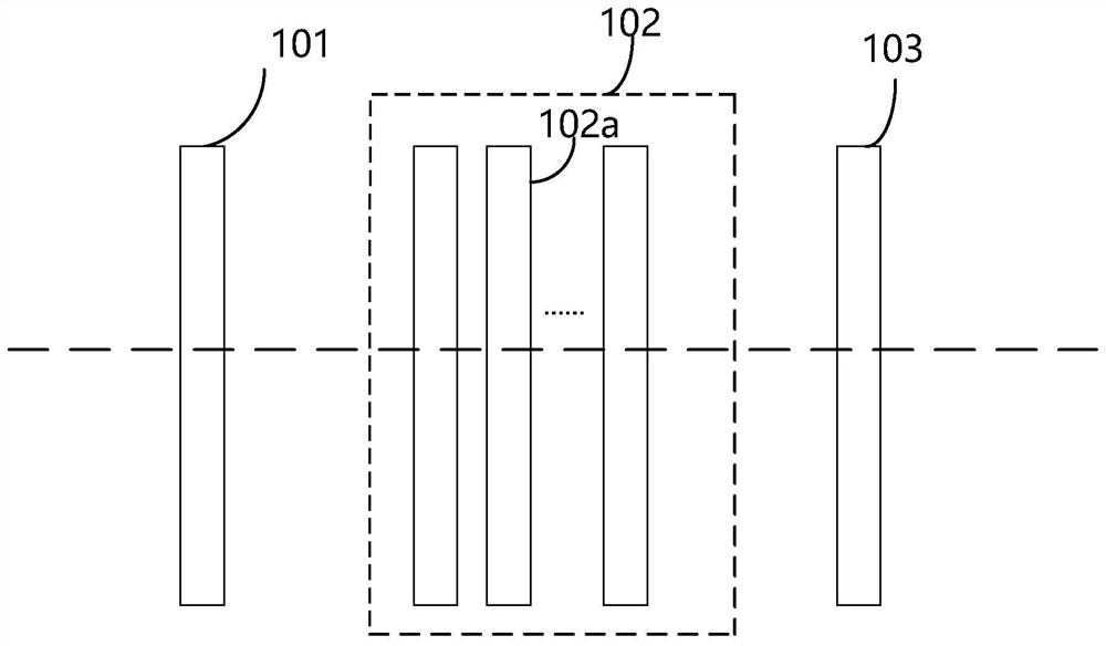
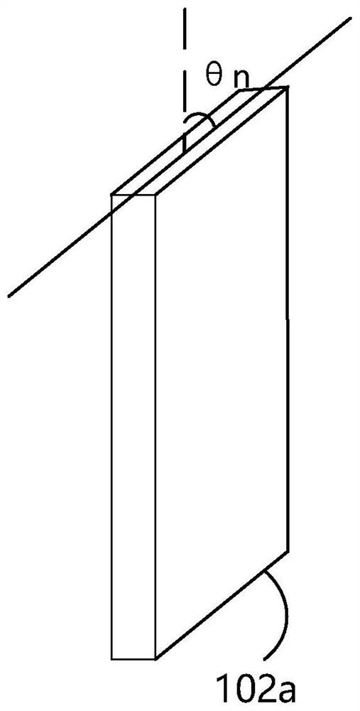
[0049] refer to figure 1 and figure 2 , this embodiment provides a method for determining the parameters of a multi-channel variable wavelength polarization interference filter. The polarization interference filter includes a polarizer 101, a phase delay crystal assembly 102, and an analyzer 103. The phase delay crystal assembly 102 includes N A crystal 102a, the polarization axis of the polarizer 101 is perpendicular or parallel to the polarization axis of the polarizer 103, polarized light is input through the polarizer 101, and then output through the analyzer 103 after being propagated through the phase delay crystal assembly 102;

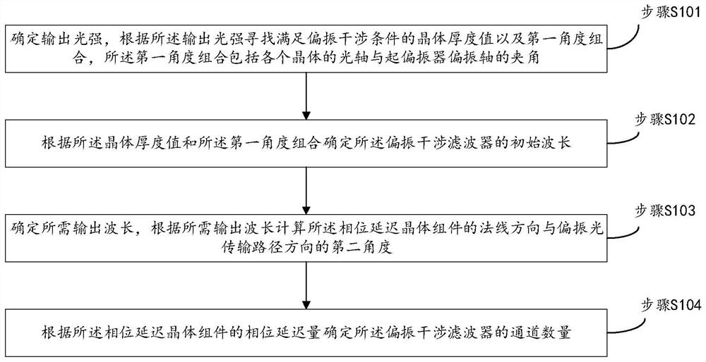
[0050] The method for determining the parameters of the polarization interference filter includes:

[0051] Step S101, determine the output light intensity, and find the crystal thickness value satisfying the polarization interference condition and the first angle combination according to the output light intensity, the first angle combinatio...

Embodiment 2

[0091] In this embodiment, the method for determining the parameters of the multi-channel variable-wavelength polarization interference filter is further described through specific application scenarios.

[0092] Taking ultraviolet light as an example, refer to figure 1 , the polarizer 101 adopts a quartz polarizing prism, the phase retardation crystal assembly 102 includes N ultraviolet quartz single crystals, and the analyzer 103 adopts a quartz prism, wherein the polarization axis of the quartz polarizing prism is perpendicular to the polarization axis of the quartz prism, and the phase retardation crystal The quartz single crystals in the component 102 have the same phase retardation, and the angle between the optical axis of the quartz single crystal and the polarization axis of the quartz polarizing prism is θ 1 , θ 2 ,... θ n .

[0093] The ultraviolet light passes through the polarizer 101, the polarized light is transmitted in the phase retardation crystal componen...


PUM


Abstract

The present invention provides a method for determining the parameters of a multi-channel variable-wavelength polarization interference filter, which includes determining the output light intensity, and finding the crystal thickness value and the first angle combination that satisfy the polarization interference condition according to the output light intensity. The first angle combination includes the angle between the optical axis of each crystal and the polarization axis of the polarizer; determine the initial wavelength of the polarization interference filter according to the crystal thickness value and the first angle combination; determine the required output wavelength, Calculate the second angle between the normal direction of the phase delay crystal component and the direction of the polarized light transmission path according to the required output wavelength; determine the number of channels of the polarization interference filter according to the phase delay of the phase delay crystal component; pass Parameter setting to realize multi-channel adjustable wavelength output.

Description

technical field [0001] The invention relates to the technical field of optical devices, in particular to a method for determining parameters of a multi-channel variable-wavelength polarization interference filter. Background technique [0002] In optical information collection and processing, optical filtering and spectrum analysis play an extremely important role. The optical filter device can select a specific spectrum or a combination of multiple separated spectrums to pass through, and is a key device for optical communication, spectral remote sensing imaging, and medical spectral diagnosis. [0003] At present, optical filter devices are mainly interference filters prepared by the principle of multi-film interference, or absorption filters prepared by dichroic materials. Interference filters and absorption filters are characterized by mature technology, high transmittance and excellent spectral response characteristics, but fixed wavelength is a shortcoming of filters,...

Claims


Application Information

Patent Timeline
Patent Type & Authority Patents(China)
IPC IPC(8): G01J1/04
CPCG01J1/0429G01J1/0488
Inventor 刘金礼
Owner 深圳市合飞科技有限公司
Why Eureka
Try Eureka