Direct current blow-type gust wind tunnel with bypass revolving door

A revolving door and gust technology, applied in the field of wind engineering, can solve problems such as inability to fully simulate random gusts in the atmospheric boundary layer

Pending Publication Date: 2019-04-16
GUODIAN ENVIRONMENTAL PROTECTION RES INST CO LTD
View PDF0 Cites 2 Cited by
  • Summary
  • Abstract
  • Description
  • Claims
  • Application Information

AI Technical Summary

Problems solved by technology

There is no wind tunnel bypass design, so the current gust wind tunnel

Method used


Image

  • Direct current blow-type gust wind tunnel with bypass revolving door
  • Direct current blow-type gust wind tunnel with bypass revolving door
  • Direct current blow-type gust wind tunnel with bypass revolving door

Examples


Embodiment 1

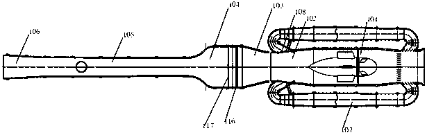
[0039] see figure 1 and figure 2 , the gust wind tunnel of the embodiment of the present invention comprises:

[0040] The power section 101, the diffuser section 103, the stable contraction section 104, the test section 105 and the outlet diffuser section 106 are connected in sequence; specifically, each of the above independent functional sections can be welded or screwed into an integral wind tunnel. Wherein: the power section 101 is communicated with a bypass section 107 , and the bypass section 107 is connected with the power section 101 with a shunt door 108 . One end of the bypass section is connected to the outlet end of the power section (also referred to as the diversion section 102 ) and a diversion door is provided at the communication point. By opening the diversion door, the air flow can be diverted from the main channel to the bypass section. The other end of the bypass section communicates with the inlet end of the power section.

[0041] Optionally, in ord...

Embodiment 2

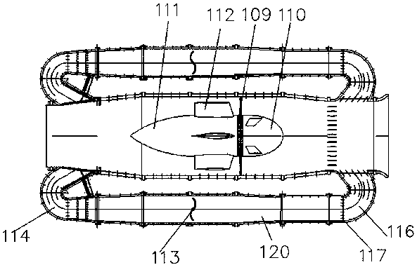
[0051] In this example, if image 3 As shown, optional bypass section 107 includes: corner front section 114 , bypass main section 120 , and corner rear section 116 . Wherein the front corner section 114 and the rear corner section 116 are all used to communicate with the power section 101; Axial. Moreover, the rotary throttle valve 113 is disposed inside the bypass main section 120 .

Embodiment 3

[0053] In this example, if image 3 As shown, the front section 114 of the corner and the rear section 116 of the corner are optionally provided with deflectors, which are used to guide the airflow and reduce the energy loss caused by the sudden change of the airflow direction. When the diverter door 108 is opened, the corner front section 114 smoothly introduces the diverted airflow to the bypass main section 120 to reduce the loss of airflow energy. The main bypass section 120 and the power section 101 are axially parallel to each other, and the rotary cut-off door 113 inside the bypass main section 120 makes the airflow velocity in the main channel change rapidly to generate gusts of wind. Then it flows back into the power section 101 through the corner rear section 116 .


PUM


Abstract

The invention discloses a direct current blow-type gust wind tunnel with a bypass revolving door. The direct current blow-type gust wind tunnel comprises a power section, a shunt section, a diffusionsection, a stable contraction section, a test section and an outlet diffusion section, wherein the power section, the shunt section, the diffusion section, the stable contraction section, the test section and the outlet diffusion section are connected in sequence. The power section is communicated with a bypass section. The front end of the bypass section is in communication with the inlet end ofthe power section. The rear end of the bypass section is in communication with the outlet end of the power section, and a shunt door is arranged at the communication joint. When the shunt door is open, airflow in the power section can enter the bypass section. A revolving intercepting door is arranged in the bypass section. The revolving intercepting gate is used to control the flow rate of main passage airflow into the bypass section, so that the airflow speed in a main passage changes rapidly, and a gust of varying magnitude is formed in the test section. According to the invention, the change speed of the gust of the test section is changed by controlling the revolving speed of the revolving door; and the gust wind tunnel provided by the invention can be used to generate the gust.

Description

technical field [0001] The invention relates to the technical field of wind engineering, in particular to a direct-flow gust wind tunnel with a revolving door with a bypass. Background technique [0002] Boundary layer wind tunnels are playing an increasingly important role in the research of wind engineering. The boundary layer wind tunnel has the ability to simulate the flow of the atmospheric boundary layer, and can provide technical support for the study of the diffusion law of atmospheric pollutants and the safety design research of many other unique structures such as long-span bridges, high-rise buildings, and towers. [0003] Boundary layer wind tunnels can be divided into blow-out wind tunnels and suction-type wind tunnels according to the flow direction of the airflow: the blow-out wind tunnel uses the airflow blown out by the fan as the flow medium of the wind tunnel; The low-pressure area formed by the rotation of the blades sucks in air to form an airflow. The...

Claims


Application Information

Patent Timeline
IPC IPC(8): G01M9/04
CPCG01M9/04
Inventor 丁力杨光俊王圣徐振田文鑫
Owner GUODIAN ENVIRONMENTAL PROTECTION RES INST CO LTD
Why Eureka
Try Eureka