Supercharge Your Innovation With Domain-Expert AI Agents!

Contact net detecting device, method and equipment

A detection equipment, catenary technology, applied in the direction of measuring devices, material analysis through optical means, instruments, etc., can solve the problems of low detection efficiency and inability to realize full-automatic detection, and achieve the effect of improving detection efficiency and accuracy

Active Publication Date: 2019-04-16
WATRIX TECH CORP LTD
View PDF6 Cites 0 Cited by
  • Summary
  • Abstract
  • Description
  • Claims
  • Application Information

AI Technical Summary

Problems solved by technology

At present, the detection method of catenary wear is to manually measure the thickness of the catenary with a caliper, so as to calculate the wear value of the catenary. This detection method has low detection efficiency and cannot realize full-automatic detection

Method used


Image

  • Contact net detecting device, method and equipment
  • Contact net detecting device, method and equipment
  • Contact net detecting device, method and equipment

Examples


Embodiment Construction

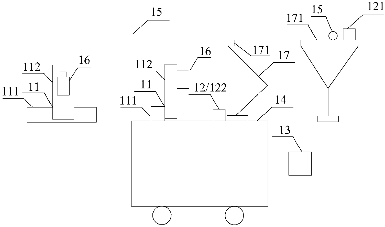
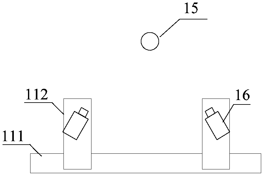
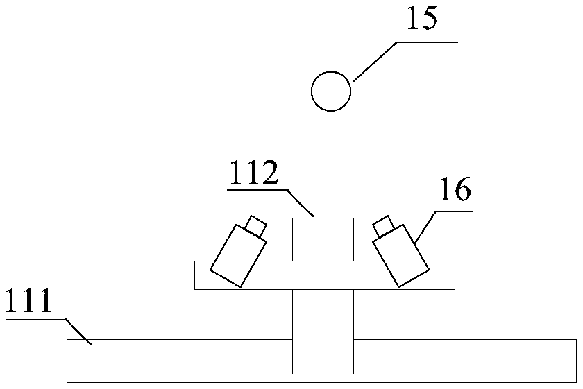
[0044] In order to make the purpose, technical solutions and advantages of the embodiments of the present application clearer, the technical solutions in the embodiments of the present application will be clearly and completely described below in conjunction with the drawings in the embodiments of the present application. Obviously, the described embodiments are only It is a part of the embodiments of this application, not all of them. The components of the embodiments of the application generally described and illustrated in the figures herein may be arranged and designed in a variety of different configurations. Accordingly, the following detailed description of the embodiments of the application provided in the accompanying drawings is not intended to limit the scope of the claimed application, but merely represents selected embodiments of the application. Based on the embodiments of the present application, all other embodiments obtained by those skilled in the art without...


PUM


Abstract

The invention provides a contact net detecting device, method and equipment. The device comprises a linear motion mechanism, a distance sensor unit and a processor. The linear motion mechanism comprises a lateral linear motion mechanism and a longitudinal linear motion mechanism slidingly connected therewith. The longitudinal linear motion mechanism is slidingly connected with a data acquisition device. The distance sensor unit comprises a first distance sensor and a second distance sensor. The first distance sensor is used for collecting the lateral distance between a contact net and the first distance sensor. The second distance sensor is used for collecting the longitudinal distance between the slide of a pantograph and the second distance sensor. The processor is used to control the linear motion mechanisms to move the data acquisition device to a preset relative position below the contact net according to the lateral distance and the longitudinal distance to ensure that the relative position of the data acquisition device and the contact net is unchanged. Full-segment full-automatic detection of the contact net can be realized during the running process of a detecting vehicle,and the detection efficiency and accuracy are improved.

Description

technical field [0001] The present application relates to the technical field of catenary detection, in particular to a catenary detection equipment, method and device. Background technique [0002] The catenary is a high-voltage transmission line that is erected in a zigzag shape along the sky above the rails in the electrified railway to obtain current for the pantograph of the electric traction locomotive (such as the subway). When the electric traction locomotive is running, the pantograph on the roof is in contact with the catenary. Due to the relative movement between the catenary and the pantograph, it will cause a certain degree of wear on the lower part of the catenary. [0003] After the catenary is worn below, it will affect the pantograph’s current intake, thereby affecting the normal operation of the locomotive. Therefore, it is necessary to regularly detect the wear of the catenary, so that it can be replaced in time when it is worn to a certain extent. At pre...

Claims


Application Information

Patent Timeline
Patent Type & Authority Applications(China)
IPC IPC(8): G01N21/84
CPCG01N21/84
Inventor 黄永祯崔东胜
Owner WATRIX TECH CORP LTD
Features
  • R&D
  • Intellectual Property
  • Life Sciences
  • Materials
  • Tech Scout
  • Unparalleled Data Quality
  • Higher Quality Content
  • 60% Fewer Hallucinations
Learn More