GNSS (Global Navigation Satellite System) receiver-based time service method and GNSS (Global Navigation Satellite System) receiver

A receiver and time technology, applied in the field of satellite timing, can solve the problem that the output accuracy of PPS does not meet the requirements, etc.

Active Publication Date: 2019-04-16
UNICORE COMM INC +1
11 Cites 0 Cited by

AI-Extracted Technical Summary

Problems solved by technology

It can be seen that the PPS output accuracy of mainstream GNSS ...

Method used

In an exemplary embodiment, before using the local clock drift data that this PVT operation obtains to correct the difference, the timing method of the present embodiment can also include: filter the difference in the following way: when If the difference is greater than the set threshold, the first bandwidth is used to filter the difference; when the difference is less than or equal to the set threshold, the second bandwidth is used to filter the difference; wherein, the first bandwidth is greater than the second Two bandwidth. Exemplarily, the first bandwidth may be 0.4 hertz (Hz), and the second bandwidth may be 0.13 Hz. In this exemplary embodiment, by adopting a dynamic bandwidth adjustment manner to filter the difference, the convergence can be accelerated and the accuracy of the subsequent processing can be improved.
The embodiment of the present application provides a kind of time service method and GNSS receiver based on GNSS receiver, on the basis of GNSS receiver, use the frequency pr...

Abstract

The present invention discloses a GNSS (Global Navigation Satellite System) receiver-based time service method and a GNSS (Global Navigation Satellite System) receiver. The time service method includes the following steps that: the PVT local time of one or more navigation systems and local clock drift data are obtained through PVT operation; the PPS of whole-second time corresponding to the PVT operation completion time of the current PVT operation is obtained; and the difference value of the PVT local time of any one navigation system which is obtained through the current PVT operation and the PPS of the whole-second time is calculated, and the difference value is corrected with the local clock drift data which are obtained through the current PVT operation, and the PPS of the next secondis outputted according to the difference value.

Application Domain

Radio-controlled time-pieces

Technology Topic

Environmental geologyMarine navigation +3

Image

  • GNSS (Global Navigation Satellite System) receiver-based time service method and GNSS (Global Navigation Satellite System) receiver
  • GNSS (Global Navigation Satellite System) receiver-based time service method and GNSS (Global Navigation Satellite System) receiver
  • GNSS (Global Navigation Satellite System) receiver-based time service method and GNSS (Global Navigation Satellite System) receiver

Examples

  • Experimental program(1)

Example Embodiment

[0019] Embodiments of the present application will be described in detail below in conjunction with the accompanying drawings. It should be noted that, in the case of no conflict, the embodiments in the present application and the features in the embodiments can be combined arbitrarily with each other.
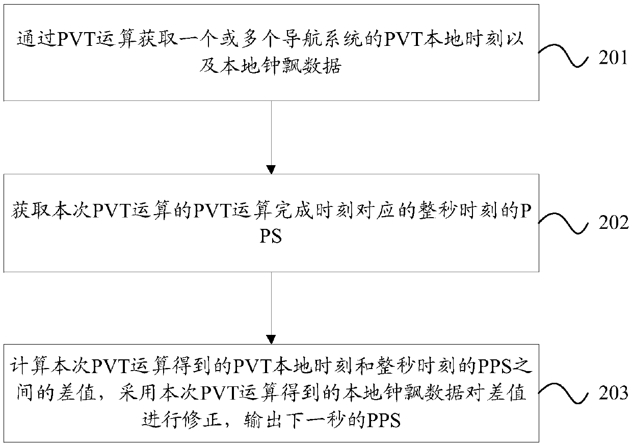
[0020] The steps shown in the flowcharts of the figures may be performed in a computer system, such as a set of computer-executable instructions. Also, although a logical order is shown in the flowcharts, in some cases the steps shown or described may be performed in an order different from that shown or described herein.
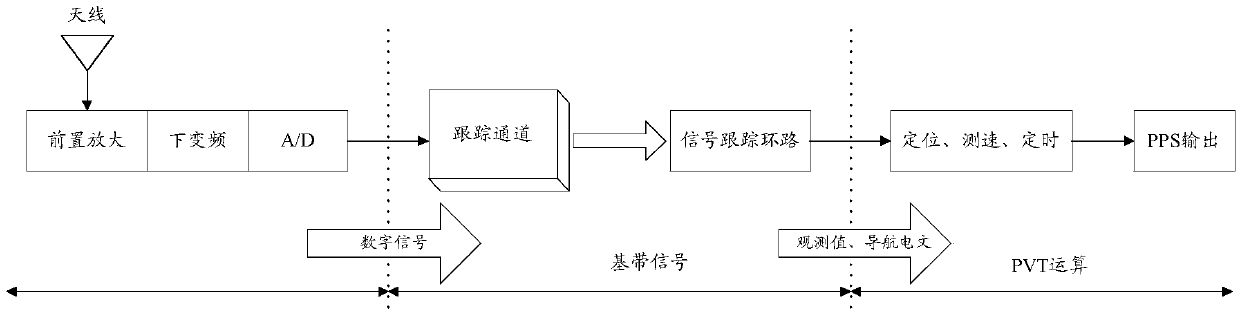
[0021] figure 1 It is a schematic diagram of the principle of the timing GNSS receiver. like figure 1 As shown, after the time service GNSS receiver receives the GNSS satellite signal through the antenna, it can perform pre-amplification, down-conversion and analog-to-digital (A/D) conversion processing on the received satellite signal, so as to convert the radio frequency satellite signal received by the antenna It is a digital signal; then baseband processing is performed on the converted digital signal. In the baseband processing process, the navigation signal of the target satellite is captured and tracked through the tracking channel and the signal tracking loop, and the observation information and navigation message are obtained according to the tracked navigation signal of the target satellite. Afterwards, the position, velocity, time and other positioning results of the time-service GNSS receiver can be obtained by calculating the position, velocity and time (PVT, Position Velocity and Time), and then drive the local PPS clock to output the second pulse (PPS) signal, through the PPS The signal realizes precise timing.
[0022] However, due to the cost, power consumption and size limitations of the current time-serving GNSS receivers, it is impossible to use expensive and large-scale constant temperature crystal oscillators on a large scale. Generally, TCXOs with temperature compensation are used, and TCXOs are easy to Affected by the environment, temperature, etc., the second stability value is relatively poor, which will have a greater impact on the calculated time accuracy when applied to timing technology.
[0023] The embodiment of the present application provides a timing method based on a GNSS receiver and a GNSS receiver. On the basis of the GNSS receiver, a frequency pre-compensation method based on a second is used to correct the local PSS, thereby significantly improving the accuracy of the PPS and achieving high Accurate timing. The timing method based on the GNSS receiver provided in this embodiment can provide a PPS used as a time reference for many applications. For example, it can be applied in many scenarios that require a time reference, such as time calibration in 4G and 5G mobile communications, time synchronization of base stations, and time synchronization of power systems.
[0024] figure 2 It is a schematic diagram of the timing method based on the GNSS receiver provided by the embodiment of the present application. like figure 2 As shown, the timing method based on the GNSS receiver provided by this embodiment includes the following steps:
[0025] Step 201, obtain PVT local time and local clock drift data of one or more navigation systems through PVT calculation;
[0026] Step 202, obtain the PPS at the whole second time corresponding to the PVT operation completion time of this PVT operation;
[0027] Step 203, calculate the difference between the PVT local time obtained by this PVT operation and the PPS at the corresponding whole second time, use the local clock drift data obtained by this PVT operation to correct the difference, and output the PPS of the next second PPS.
[0028] Wherein, the navigation system may include at least one of the following: GPS, GLONASS, BeiDou, Galileo. In an exemplary embodiment, the system-wide multi-frequency GNSS receiver can simultaneously receive signals of multiple frequency points of all four navigation systems, thereby obtaining multi-frequency clock error data of all navigation systems. However, the present application is not limited to this. In practical applications, GNSS receivers can receive satellite signals of one or more navigation systems according to actual conditions.
[0029] In an exemplary embodiment, step 201 may include: acquiring PVT calculation time and clock data of at least one navigation system obtained by PVT calculation; Data to determine the PVT local time corresponding to this PVT operation. For example, the PVT local time of the GPS system obtained by this PVT operation can be determined according to the sum of the PVT solution time obtained by this PVT operation and the clock difference data of the GPS system.
[0030] In an exemplary embodiment, step 202 may include: obtaining the PPS maintained by the local PPS counter; using the PPS maintained by the local PPS calculator to subtract the difference between the whole second moment and the PVT operation completion time of this PVT operation , to obtain the calculated value of the PPS at the whole second time; the calculated value is corrected by using the local clock drift data obtained by this PVT calculation, and the corrected PPS at the whole second time is obtained.
[0031] In this exemplary embodiment, the calculated value is corrected by using the local clock drift data obtained by this PVT calculation, and the corrected PPS at the whole second time may include: the local clock drift obtained based on this PVT calculation Data, according to the following formula to get the corrected PPS at the whole second time:
[0032] T PPS (n)=T PPS (n+tp )-T PVT (n+t p )×(1+F d (n));
[0033] Among them, T PPS (n) indicates the PPS of the nth second; T PVT (n+t p ) means n+t p PVT local time corresponding to time; T PPS (n+t p ) means n+t p PPS corresponding to time; F d (n) represents the local clock drift data obtained by the PVT operation of the nth second; t p Indicates the PVT operation completion time corresponding to the nth second; n is a positive integer.
[0034] In an exemplary embodiment, in step 203, the difference is corrected by using the local clock drift data obtained by this PVT operation, and the PPS of the next second is output, which may include:
[0035] Correct the difference between the PVT local time obtained by the PVT calculation of the nth second and the PPS at the nth second according to the following formula:
[0036] Δt(n)=T PVT (n)-T PPS (n)=T PVT (n)-(T PPS (n+t p )-T PVT (n+t p )×(1+F d (n)));
[0037] Among them, T PVT (n) represents the PVT local time obtained by the PVT operation of the nth second; T PPS (n) represents the PPS at the nth second; T PVT (n+t p ) means n+t p PVT local time corresponding to time; T PPS (n+t p ) means n+t p PPS corresponding to time; F d (n) represents the local clock drift data obtained by the PVT operation of the nth second; t p Indicates the completion time of the PVT operation corresponding to the nth second; n is a positive integer;
[0038] Among them, based on the corrected difference, the PPS of the n+1th second is output according to the following formula:
[0039]
[0040] In an exemplary embodiment, before using the local clock drift data obtained by this PVT operation to correct the difference, the timing method of this embodiment may further include: filtering the difference in the following manner: when the difference is greater than Setting a threshold value, using the first bandwidth to filter the difference; when the difference is less than or equal to the set threshold value, using the second bandwidth to filter the difference; wherein, the first bandwidth is greater than the second bandwidth. Exemplarily, the first bandwidth may be 0.4 hertz (Hz), and the second bandwidth may be 0.13 Hz. In this exemplary embodiment, by adopting a dynamic bandwidth adjustment manner to filter the difference, the convergence can be accelerated and the accuracy of the subsequent processing can be improved.
[0041] The following uses an example to illustrate the timing method provided in the embodiment of the present application. In this exemplary embodiment, a system-wide multi-frequency point GNSS receiver is taken as an example for illustration.
[0042] The timing method provided by this exemplary embodiment includes the following processes:
[0043] Step 1: After the GNSS receiver performs PVT calculation locally, it obtains local positioning coordinates, PVT solution time, four system clock differences, and local clock drift data. Among them, the GNSS receiver can simultaneously receive multiple frequency point signals of all four navigation systems, thereby obtaining multi-frequency clock error data of the four navigation systems. Among them, for any PVT calculation, the PVT local time of any navigation system can be determined according to the PVT solution time obtained by this PVT calculation and the clock difference data of the navigation system, for example, the PVT local time of the navigation system is equal to the PVT solution time The sum of the time and the clock data of the navigation system.
[0044] Step 2: Making a difference between the clock difference data of the four navigation systems in pairs to obtain clock difference data between different navigation systems.
[0045] Step 3: selecting the clock data of the corresponding navigation system by optimizing the frequency points of the navigation system used by the algorithm or configuring by the user. Wherein, the selection of the clock error data no matter adopts algorithm optimization or user configuration, when the clock error data of the frequency point of the selected navigation system does not exist due to interference and other reasons, the clock error data of other navigation systems can be selected by polling, and use step 2 Compensate the clock difference data in the system to obtain the clock difference data of the corresponding navigation system. In this way, this exemplary embodiment can support automatic optimization selection and user configuration selection of the navigation system for high-precision timing.
[0046] After the navigation system is selected, according to the PVT local time and local clock drift data corresponding to the selected navigation system, high-precision timing can be achieved through the following steps.
[0047] Step 4: Judging the local positioning coordinates obtained by the PVT calculation in step 1 and the sign status at the time of PVT calculation, if the sign status shows that the result is invalid, return to step 1 for the next second PVT calculation, otherwise continue to the following steps.
[0048] Step 5: Compensate the local time delay and user-set time delay for the PVT local time obtained in Step 1. Wherein, the local delay and the delay set by the user may be determined according to actual applications, which is not limited in this application.
[0049] Step 6: Obtain the local PPS maintained locally, and use the PPS at the time when the PVT calculation is completed to reversely deduce the PPS at the time of the whole second.
[0050] In this step, when deriving back the PPS at the whole second (for example, at the nth second, n is a positive integer), you can use the PPS maintained by the local PPS counter to subtract the whole second (nth second) to the PVT Completion time t p The difference between is obtained.
[0051] Wherein, due to the influence of the frequency drift of the local crystal oscillator, a frequency pre-compensation method can be used to correct the PPS at the whole second (nth second). Let the local clock drift data caused by the frequency drift of the local crystal oscillator obtained by PVT this time (for example, at the nth second) be F d (n), then the correction value of the PPS at the whole second moment (the nth second) can be:
[0052] T PPS (n)=T PPS (n+t p )-T PVT (n+t p )×(1+F d (n));
[0053] Among them, T PPS (n) represents the PPS at the nth second; T PVT (n+t p ) means n+t p PVT local time corresponding to time; T PPS (n+t p ) means n+t p PPS corresponding to time; t p Indicates the PVT calculation completion time corresponding to the nth second.
[0054] Step 7, obtain the difference between the PPS of the PVT local time after the time delay compensation in step 5 and the PPS of the whole second moment (n second) obtained in step 6, i.e. Δt(n)=T PVT (n)-T PPS (n).
[0055] Step 8: Perform loop filtering on the difference Δt(n) at the nth second obtained in step 7 to filter out noise, and use the frequency pre-compensation method to correct it, so as to obtain the precise PPS at the n+1th second , and then output the precise PPS at the n+1th second.
[0056] Among them, when performing noise filtering through loop filtering, the larger the bandwidth of the filter, the less noise is filtered out, but the time response is more timely; the smaller the bandwidth of the filter, the better the effect of filtering noise, but the time response is more timely long. Therefore, in this step, feedback based on the output result can be adopted and a dynamic bandwidth adjustment method can be used. When Δt(n) is greater than the set threshold value, a large bandwidth (for example, 0.4Hz) is used for filtering, and filtering N times, when If Δt(n) is less than or equal to the set threshold, a small bandwidth (for example, 0.13 Hz) is used for filtering and N times of filtering; wherein, N may be an integer greater than 1. In other words, use a large bandwidth of 0.4Hz for filtering when you just get it or just pull it back, and use a small bandwidth of 0.13Hz for filtering when the output accuracy reaches a certain level; this can not only speed up convergence, but also have higher timing accuracy in the later stage.
[0057] In this step, the correction based on the frequency pre-compensation may use the local clock drift data obtained in the current second (nth second) for correction. The PPS of the n+1th second can be:
[0058]
[0059] Among them, T PVT (n) represents the PVT local time obtained by PVT calculation in the nth second; T PPS (n) represents the PPS at the nth second; T PVT (n+t p ) means n+t p PVT local time corresponding to time; T PPS (n+t p ) means n+t p PPS corresponding to time; F d (n) represents the local clock drift data obtained by the PVT operation of the nth second; t p Indicates the PVT operation completion time corresponding to the nth second; n is a positive integer.
[0060] In this exemplary embodiment, the local PPS can be corrected based on the frequency pre-compensation mode within a second, thereby improving the timing accuracy. Moreover, this exemplary embodiment supports receiving system-wide multi-frequency point signals, supports automatic optimal selection and user configuration of navigation systems and frequency points, and performs high-precision timing, and has the advantages of flexible configuration, stable and reliable performance, and the like.
[0061] The effect of the timing method provided by the embodiment of the present application will be described below through multiple sets of test data. Among them, the measurement antenna is used for signal reception, the actual sky-to-air signal is received, and the UT4B0OEM board card applied with the timing method of the embodiment of the application and the board card without the timing method of the embodiment of the application are used to test the actual effect. Among them, the comparison between pulses can be performed through the Stanford SR60 time interval counter used for time interval measurement.
[0062] In an exemplary embodiment, at a certain moment, the difference between the PVT local time and the PPS at this second calculated by the GNSS receiver is 4.734ns after filtering, and the local clock drift data is 5.7ns/s. At the above moment, the difference after correction using the timing method provided in the embodiment of the present application is 4.733999973016200 ns.
[0063] Wherein, based on the board that does not use the timing method provided by the present embodiment, test the difference between the PPS output by the 24-hour GNSS receiver and the standard PPS of the National Time Service Center (NTSC, National Television Standards Committee), the difference between the two The comparison results between Figure 4 shown.
[0064] Figure 4 It is a schematic diagram of the comparison between the PPS output by the embodiment of the present application and the standard PPS of the National Time Service Center.
[0065] Under the same environment, based on the board card using the timing method provided by this embodiment, test the difference between the PPS output by the 24-hour GNSS receiver and the standard PPS of the National Time Service Center, the comparison results between the two can be refer to image 3 shown. image 3 It is a schematic diagram of the comparison between the PPS output by the embodiment of the present application and the standard PPS of the National Time Service Center.
[0066] refer to image 3 and Figure 4 It can be seen that, under other conditions being the same, the PPS precision deviation MTIE (Maximum Time Interval Error, maximum time interval error) of the output can be reduced from 17.5ns to 10.1ns by using the timing method of this exemplary embodiment, and 1σ from 2.294ns down to 1.382ns. It can be seen that, compared with the timing method of the traditional timing GNSS receiver, the timing accuracy obtained by using the timing method provided by this embodiment is greatly improved.
[0067] Figure 5 It is a schematic diagram of comparing the PPS output by two boards using the timing method provided by the embodiment of the present application. like Figure 5 As shown, the MTIE between the two boards is 12ns. It can be seen that the timing method provided by this embodiment has the advantage of stable and reliable performance.
[0068] Image 6 A schematic diagram of a timing device based on a GNSS receiver provided in an embodiment of the present application. like
[0069] Image 6 As shown, the timing device based on the GNSS receiver provided in this embodiment includes: a PVT calculation module 601, a PPS acquisition module 602, and a frequency pre-compensation module 603; wherein, the PVT calculation module 601 is adapted to obtain one or more The PVT local time of the navigation system and the local clock drift data; the PPS acquisition module 602 is suitable for obtaining the PPS of the whole second time corresponding to the PVT operation completion time of this PVT operation; the frequency pre-compensation module 603 is suitable for calculating this PVT operation The obtained difference between the PVT local time of the navigation system and the PPS at the whole second time is corrected by using the local clock drift data obtained by this PVT operation, and the PPS of the next second is output.
[0070] In an exemplary embodiment, the frequency precompensation module 603 may also be adapted to filter the difference in the following manner: when the difference is greater than a set threshold value, use the first bandwidth to filter the difference; is less than or equal to the set threshold value, and the difference is filtered by using the second bandwidth; wherein, the first bandwidth is greater than the second bandwidth.
[0071] For the relevant processing flow of the timing device provided in this embodiment, reference may be made to the description of the embodiment of the timing method above, so details are not repeated here.
[0072] Figure 7 The schematic diagram of the GNSS receiver provided by the embodiment of this application. like Figure 7 As shown, the GNSS receiver 700 provided by this embodiment includes: a receiver 703, a memory 701 and a processor 702; the receiver 703 is connected to the processor 302, and is suitable for receiving GNSS satellite signals; the memory 701 is suitable for storing a timing program, the When the timing program is executed by the processor 702, the steps of the timing method provided in the above-mentioned embodiments are implemented, such as figure 2 steps shown. Those skilled in the art can understand that, Figure 7 The structure shown in is only a schematic diagram of a part of the structure related to the solution of this application, and does not constitute a limitation to the GNSS receiver 700 on which the solution of this application is applied. The GNSS receiver 700 may include more than shown in the figure. More or fewer components, or combining certain components, or having a different arrangement of components.
[0073] Wherein, the processor 702 may include but not limited to a microprocessor (MCU, Microcontroller Unit) or a programmable logic device (FPGA, Field Programmable Gate Array) and other processing devices. The memory 701 can be used to store software programs and modules of application software, such as program instructions or modules corresponding to the timing method in this embodiment, and the processor 702 executes various functional applications by running the software programs and modules stored in the memory 701 And data processing, such as implementing the timing method provided by this embodiment. The memory 701 may include high-speed random access memory, and may also include non-volatile memory, such as one or more magnetic storage devices, flash memory, or other non-volatile solid-state memory. In some examples, memory 701 may include memory located remotely from processor 702 , and such remote memory may be connected to GNSS receiver 700 via a network. Examples of the aforementioned networks include, but are not limited to, the Internet, intranets, local area networks, mobile communication networks, and combinations thereof.
[0074] Regarding the relevant implementation process of the GNSS receiver provided in this embodiment, reference may be made to the description of the above method embodiment, so details are not repeated here.
[0075] In addition, the embodiment of the present application also provides a computer-readable medium, which stores a timing program based on a GNSS receiver. When the timing program is executed by a processor, the steps of the above-mentioned timing method are implemented, such as figure 2 steps shown.
[0076] Those of ordinary skill in the art can understand that all or some of the steps in the methods disclosed above, the functional modules/units in the system, and the device can be implemented as software, firmware, hardware, and an appropriate combination thereof. In a hardware implementation, the division between functional modules/units mentioned in the above description does not necessarily correspond to the division of physical components; for example, one physical component may have multiple functions, or one function or step may be composed of several physical components. Components cooperate to execute. Some or all of the components may be implemented as software executed by a processor, such as a digital signal processor or microprocessor, or as hardware, or as an integrated circuit, such as an application specific integrated circuit. Such software may be distributed on computer readable media, which may include computer storage media (or non-transitory media) and communication media (or transitory media). As known to those of ordinary skill in the art, the term computer storage media includes both volatile and nonvolatile media implemented in any method or technology for storage of information, such as computer readable instructions, data structures, program modules, or other data. permanent, removable and non-removable media. Computer storage media includes, but is not limited to, RAM, ROM, EEPROM, flash memory or other memory technology, CD-ROM, digital versatile disk (DVD) or other optical disk storage, magnetic cartridges, tape, magnetic disk storage or other magnetic storage devices, or can Any other medium used to store desired information and which can be accessed by a computer. In addition, as is well known to those of ordinary skill in the art, communication media typically embodies computer readable instructions, data structures, program modules, or other data in a modulated data signal such as a carrier wave or other transport mechanism, and may include any information delivery media .

PUM

no PUM

Description & Claims & Application Information

We can also present the details of the Description, Claims and Application information to help users get a comprehensive understanding of the technical details of the patent, such as background art, summary of invention, brief description of drawings, description of embodiments, and other original content. On the other hand, users can also determine the specific scope of protection of the technology through the list of claims; as well as understand the changes in the life cycle of the technology with the presentation of the patent timeline. Login to view more.
Why Eureka
Try Eureka