Antenna structure and communication terminal
An antenna structure and communication terminal technology, applied in the field of communication, can solve the problems of large antenna impedance mismatch loss, poor antenna transmission efficiency, etc.
- Summary
- Abstract
- Description
- Claims
- Application Information
AI Technical Summary
Problems solved by technology
Method used
Image
Examples
Embodiment 1
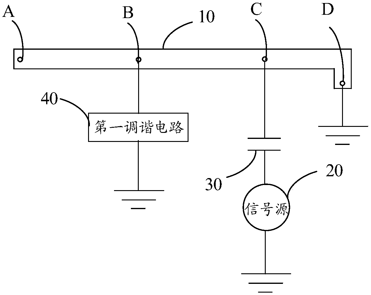
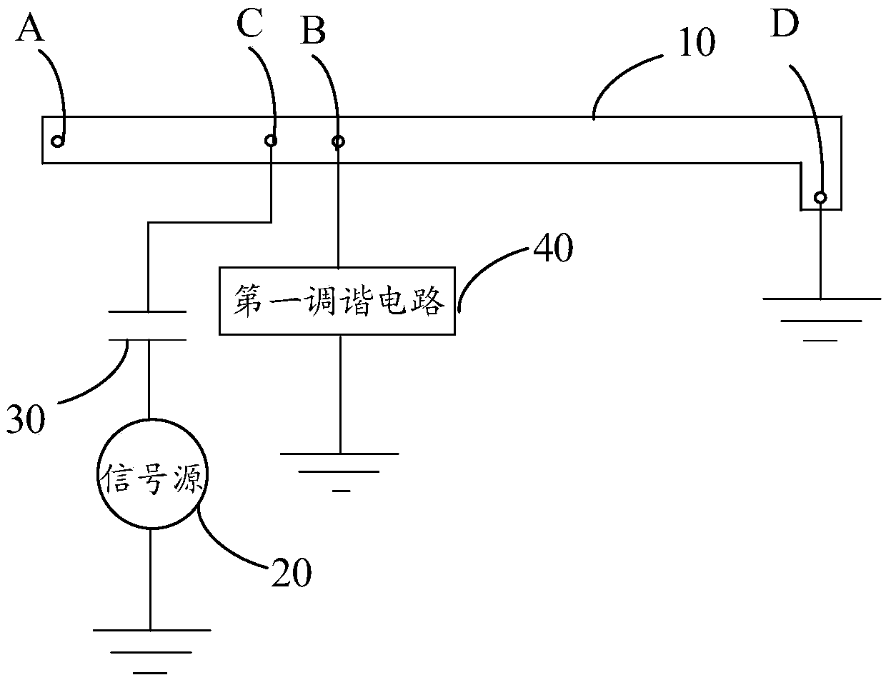
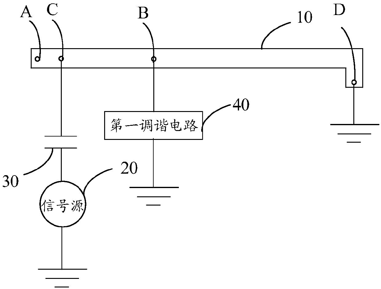
[0150] The antenna structure of the first embodiment can refer to Figure 6 shown. It should be noted that, in this embodiment, an example in which the antenna radiator is a medium-high frequency antenna radiator is used for illustration.
[0151] exist Figure 6 In the antenna radiator, a series of small capacitors C1 at the feed point C of the antenna radiator can realize the coverage of the antenna bandwidth. Wherein, the value range of C1 may be 0.5-2.7 pf, preferably, the value range of C1 may be 0.8-1.5 pf. It should be understood that C1 is equivalent to the aforementioned first capacitor.
[0152] The first tuning circuit includes K1, K2, L1 and L2. It should be understood that K1 is equivalent to the aforementioned second switch, K2 is equivalent to the aforementioned third switch, L1 is equivalent to the aforementioned second inductor, and L2 is equivalent to the aforementioned third inductor.
[0153] In the specific implementation, K1 and K2 are all off (that ...
Embodiment 2
[0175] The main difference between this embodiment and Embodiment 1 is that a second tuning circuit is newly added, and the second tuning circuit in this embodiment is mainly used to implement dual-resonance carrier aggregation (Carrier Aggregation, CA).
[0176] Such as Figure 10 As shown, the second tuning circuit in this embodiment includes K3, L3 and C2. Wherein, K3 is equivalent to the aforementioned first switch, L3 is equivalent to the aforementioned first inductor, and C2 is equivalent to the aforementioned second capacitor.
[0177] In specific implementation, when K1 is turned on, K2 is not turned on (that is, in the state of H1 or H2), and when K3 is turned on, the antenna radiator can generate two new resonant modes H5 and H6, which exist at the same time and can be used for Cover the CA requirements of B39+B41.
[0178] When both K1 and K2 are off and only K3 is on, the antenna radiator can be used to cover the CA requirements of B3+B40.
[0179] Among them, t...
Embodiment 3
[0185] The main difference between this embodiment and Embodiment 1 is that a second tuning circuit is newly added, and the second tuning circuit in this embodiment is mainly used to adjust the resonance frequency of the target resonance mode of the antenna structure and improve the performance of the target resonance mode. The antenna standing wave ratio of the target frequency band reduces mismatch loss.
[0186] Such as Figure 13 As shown, the second tuning circuit in this embodiment includes K3 and C2 connected in series. Wherein, K3 is equivalent to the aforementioned first switch, and C2 is equivalent to the aforementioned second capacitor. The second tuning circuit of this embodiment can be used to adjust the resonant frequency of H2 and H3, so as to better improve the antenna standing wave ratio of B39 and B40 and reduce the mismatch loss. If C2 is turned on, the resonant frequency of H2 and H3 will decrease.
PUM
 Abstract
Description
Claims
Application Information
 - R&D
- Intellectual Property
- Life Sciences
- Materials
- Tech Scout
- Unparalleled Data Quality
- Higher Quality Content
- 60% Fewer Hallucinations
Browse by: Latest US Patents, China's latest patents, Technical Efficacy Thesaurus, Application Domain, Technology Topic, Popular Technical Reports.
© 2025 PatSnap. All rights reserved.Legal|Privacy policy|Modern Slavery Act Transparency Statement|Sitemap|About US| Contact US: help@patsnap.com


