Rolling contact rotary electrical connector

A rolling contact, internal conduction technology, applied in the direction of rotating current collectors, circuits, connections, etc., can solve problems such as increased wear, power supply short-circuit failure, affecting service life, etc., to achieve long working life, reduce friction and wear, and good electrical contact performance effect

Inactive Publication Date: 2019-04-16
SHANGHAI AEROSPACE SYST ENG INST
View PDF4 Cites 7 Cited by
  • Summary
  • Abstract
  • Description
  • Claims
  • Application Information

AI Technical Summary

Problems solved by technology

In this design form, due to the sliding friction between the brush and the conductive ring, there is inevitable wear between the brush and the conductive ring during rotation, which greatly affects the service life. Life expectancy will be greatly reduced
At the same time, due to the existence of wear and tear, the stability of power transmission will also decrease after long-term work, and a large amount of wear debris accumulation can easily cause the insulation performance of power transmission to decline, thereby causing short-circuit faults in the power supply

Method used


Image

  • Rolling contact rotary electrical connector
  • Rolling contact rotary electrical connector
  • Rolling contact rotary electrical connector

Examples


Embodiment Construction

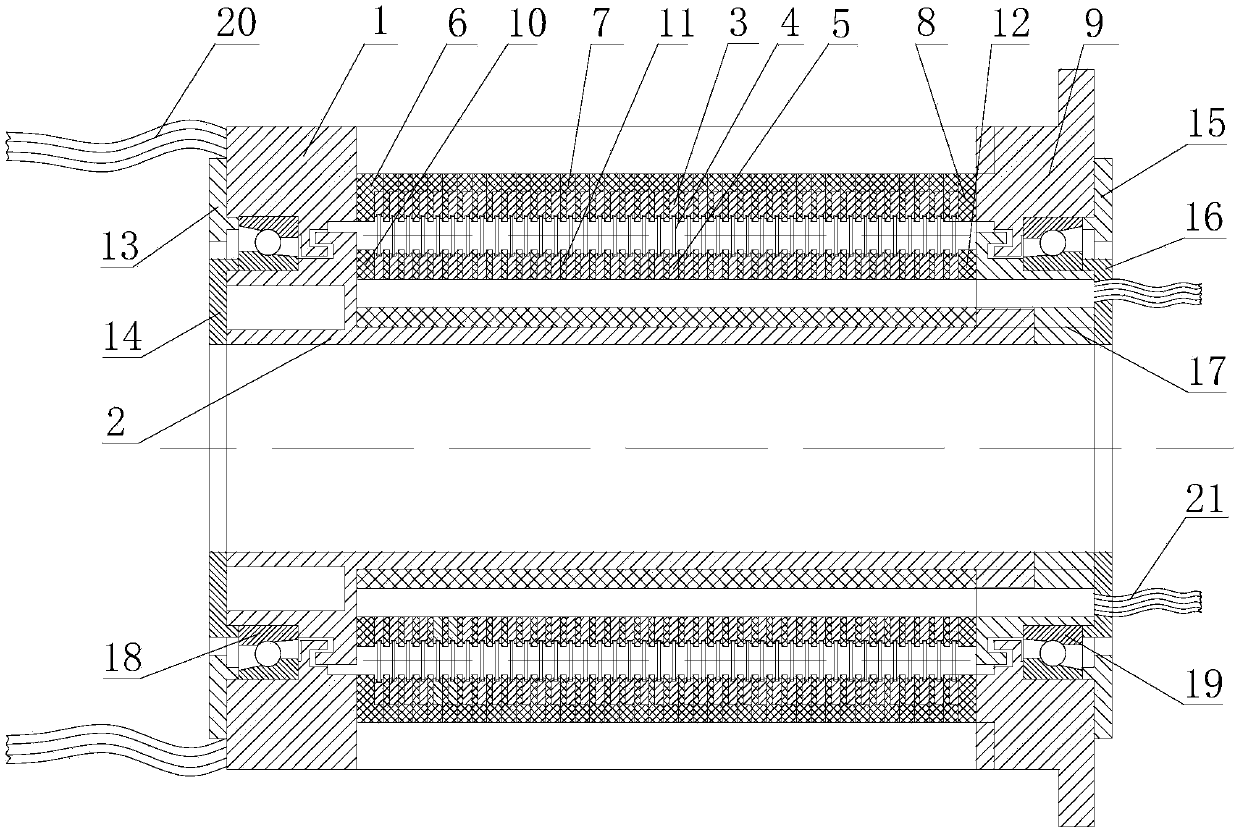
[0018] The following will combine Figure 1 ~ Figure 3 The rolling contact rotary electrical connector of the present invention is further described in detail.

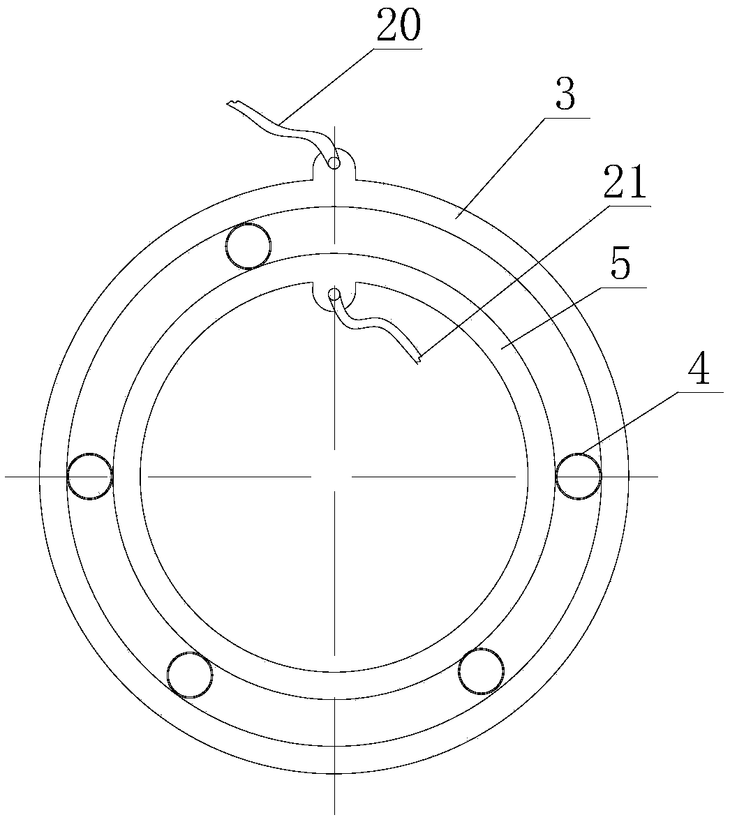
[0019] figure 1 Shown is a schematic cross-sectional view of the structure of the rolling contact rotary electrical connector; the outer conductive ring 3 is set on the housing 1, and the insulation between the outer conductive ring 3 and the housing 1 is realized through the insulating rings 6, 7, 8, and each outer conductive ring For mutual insulation, the outer conductive ring, the insulating ring and the shell are connected as a whole through the flange 9 .

[0020] The inner conductive ring 5 is sleeved on the shaft 2, the insulation between the inner conductive ring 5 and the shaft 2 and the mutual insulation between the inner conductive rings are realized through the insulating rings 10, 11, 12, and the inner conductive ring, the insulating ring and the The shaft is connected as a whole. The flexible ring 4 ...


PUM


Abstract

The invention discloses a rolling contact rotary electrical connector. The rolling contact rotary electrical connector comprises a shell, a shaft, a shaft sleeve, an end cover, an inner conductive ring, an outer conductive ring, flexible rings, an insulating ring, a bearing and an output lead, wherein the inner conductive ring and the outer conductive ring are connected with leads for the transmission of signals and power; a proper number of flexible rings are arranged between the inner conductive ring and the outer conductive ring according to the need; and the flexible rings keep contact with the working faces of the inner conductive ring and the outer conductive ring by means of elastic deformation. The inner conductive ring is mounted on the shaft, the outer conductive ring is mountedon the shell, and a bearing is mounted between the shaft and the shell to achieve relative rotation and drive the flexible rings to rotate, thus realizing the continuous transmission of signals from the inner conductive ring to the outer conductive ring. By rolling the flexible rings relative to the inner conductive ring and the outer conductive ring, the transmission of signals and power is realized, so that the friction and wear during rotating operation can be reduced greatly, and the service life of the rolling contact rotary electrical connector can reach more than five times of that of the traditional rotary electrical connector at the same rotating speed.

Description

technical field [0001] The invention relates to a rotary electrical connector, in particular to a rolling contact type rotary electrical connector. Background technique [0002] The rotary electrical connector is an electrical connector that can transmit signals and power in a rotating state. It can avoid damage caused by cable twisting during the rotating electrical transmission process. It is widely used in the rotating electrical transmission between the fixed end and the rotating end of the equipment. [0003] The traditional rotary electrical connector is mainly composed of a conductive ring and a brush. The conductive ring and the brush rotate relative to each other. The brush maintains sliding contact with the conductive ring under a certain pressure, thereby realizing the transmission of signals and power. In this design form, due to the sliding friction between the brush and the conductive ring, there is inevitable wear between the brush and the conductive ring duri...

Claims


Application Information

Patent Timeline
Patent Type & Authority Applications(China)
IPC IPC(8): H01R39/34
CPCH01R39/34
Inventor 李超李兆陈秀群李长江戴飞朱雪龙
Owner SHANGHAI AEROSPACE SYST ENG INST
Why Eureka
Try Eureka