Stator sheet collecting device

A technology of collecting device and stator sheet, which is applied in the direction of manufacturing stator/rotor body, etc., can solve the problems such as difficulty in placing and collecting the stator sheets neatly, and achieve the effect of facilitating the pressing process

Pending Publication Date: 2019-04-16
无锡新瑞驰科技有限公司
View PDF1 Cites 2 Cited by
  • Summary
  • Abstract
  • Description
  • Claims
  • Application Information

AI Technical Summary

Problems solved by technology

[0004] Although this sorting and collecting device for stator punching blanks has the advantages of simple structure, convenient use and the ability to sort and select, the stator punching blanks can be automatically sorted and selected by the device, which reduces the labor intensity of the staff, improves the selection speed, and has high work efficiency and high production efficiency. The cost is reduced, but often the stator needs to be collected and then extruded, but it is difficult to arrange and collect the stator pieces neatly

Method used


Image

  • Stator sheet collecting device
  • Stator sheet collecting device

Examples


Embodiment 1

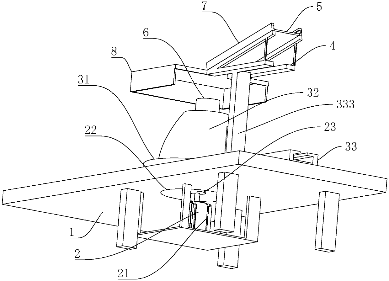
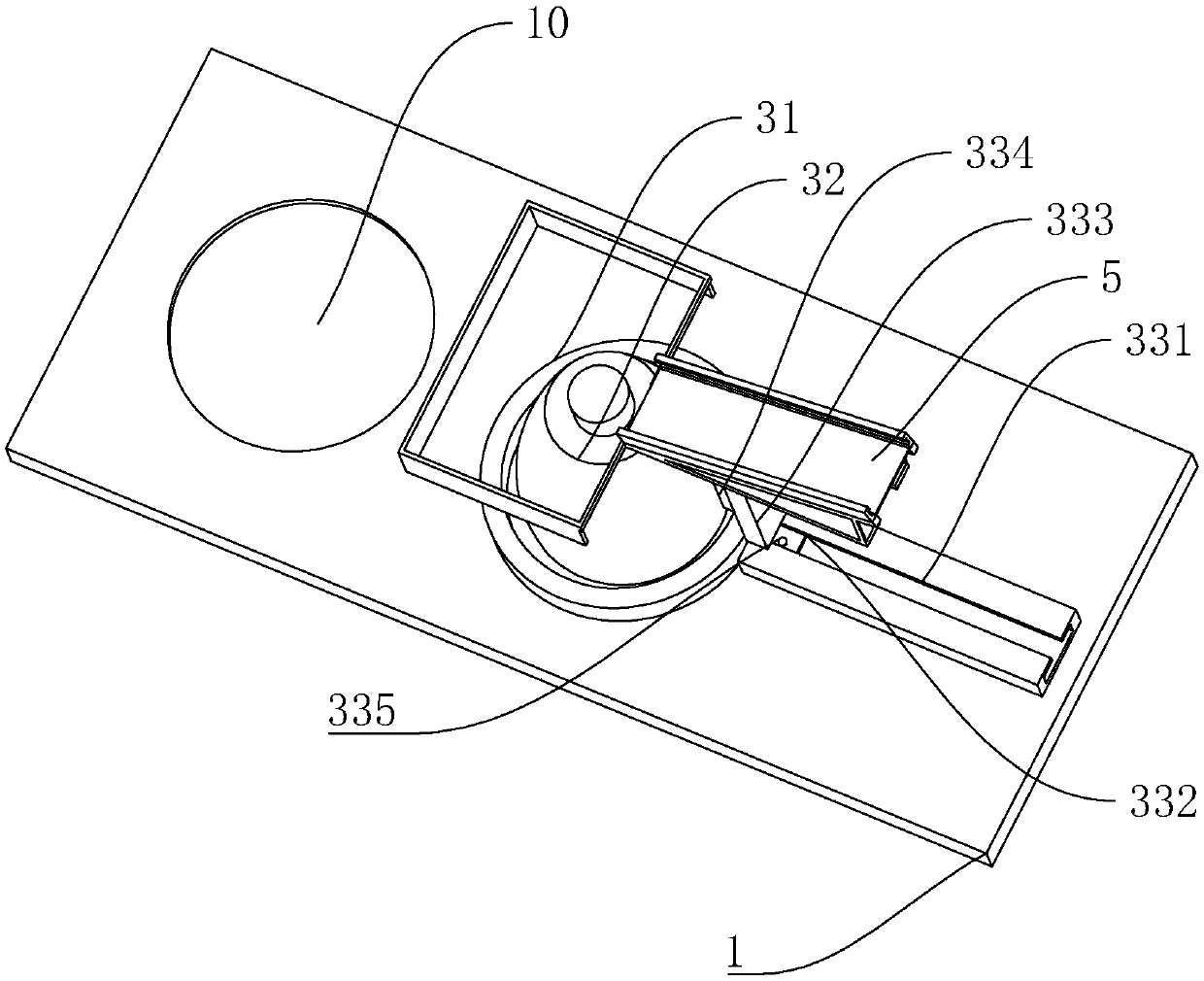
[0026] Example 1: A stator sheet collection device, such as figure 1 and figure 2 As shown, the base 1 is included. The base 1 is also provided with a placement slot 10, and the base 1 is provided with a rotating device 2. The rotating device 2 includes a rotating motor 21 located below the base 1, and a through hole 22 located on the placing plate 31 And a rotating rod 23 located at the outlet of the rotating motor 21 through the through hole 22 and fixedly connected to the rotating roller 32. The rotating device 2 is also provided with a placing device 3, and the placing device 3 includes a placing plate 31 on the rotating device 2, which is located on the placing plate The rotating roller 32 on 31 and connected to the rotating device 2 and the limiting device 33 on the side where the disk 31 is placed, and the limiting device 33 includes a chute 331 on the side where the disk 31 is placed. At the same time, the sliding block 332 is close to the supporting rod 333 provided a...


PUM


Abstract

The invention discloses a stator sheet collecting device, so as to provide a collecting device for stacking stators effectively. In the technical scheme, the stator sheet collecting device comprises abase; a rotating device is arranged on the base; a placing device is also arranged on the rotating device; the placing device comprises a placing disc located on the rotating device, a rotating roller located on the placing disc and connected with the rotating device and a limiting device located at one side of the placing disc; and the limiting device comprises a sliding groove located at one side of the placing disc, a sliding block located in the sliding groove, a supporting rod located at one end, close to the placing disc, of the sliding block, a limiting block located at one side, closeto the placing disc, of the supporting rod and a limiting screw rod located on the sliding block and passing through the sliding block to the bottom part of the sliding groove.

Description

Technical field [0001] The invention relates to the field of electrical equipment manufacturing, and in particular to a stator sheet collection device. Background technique [0002] In simple terms: the fixed part of the motor is called the stator, on which a pair of DC-excited stationary main magnetic poles are installed; and the rotating part (rotor-rotor) is called the armature core, which is to be installed The armature winding generates an induced electromotive force after being energized and acts as a rotating magnetic field. After that, an electromagnetic torque is generated for energy conversion. It is distinguished by the shape of the stator winding and the embedded method. The stator winding is different according to the shape of the coil winding and the embedded wiring method. Divided into two types: centralized and distributed. [0003] At present, the Chinese patent with publication number CN204912551U discloses a sorting and collecting device for stator punching blan...

Claims


Application Information

Patent Timeline
Patent Type & Authority Applications(China)
IPC IPC(8): H02K15/02
CPCH02K15/02
Inventor 华胜杰张建平
Owner 无锡新瑞驰科技有限公司
Why Eureka
Try Eureka