[0008]According to the first aspect, in the control circuit substrate, the
driver circuit and the temperature detection circuit are placed so as to overlap the mount region of the one of the upper arm and the lower arm, and the driver circuit and the current detection circuit are placed so as to overlap the mount region of the other arm. That is, in the control circuit substrate, the current detection circuit is placed in a region where the temperature detection circuit is not placed and thus there is room. Thus, an increase in substrate area of the control circuit substrate can be suppressed even through the current detection circuit is placed on the control circuit substrate. Moreover, suppressing an increase in substrate area can also suppress an increase in overall size of the inverter device. Thus, according to this configuration, the current detection circuit can be efficiently placed on the control circuit substrate while suppressing an increase in device size.
[0011]On the other hand, the control circuit that generates the
control signal needs to supply the
control signal to the driver circuit formed so as to overlap the mount regions of the upper arm and the lower arm. Thus, it is preferable that the control circuit be placed in the low-
voltage circuit region that is formed so as to overlap the
intermediate region between the mount region of the upper arm and the mount region of the lower arm. That is, it is preferable that the control circuit be placed at a position balanced with respect to both arms. The current detection circuit that detects the current without contacting the
alternating current power line can easily transmit a detection result to the control circuit without via an insulating circuit or a
voltage conversion circuit, if the current detection circuit operates by the same power supply
system as the control circuit. Thus, the current detection circuit is placed in the low-
voltage circuit region. As described above, however, of those regions overlapping the mount regions of the upper arm and the lower arm, the current detection circuit is placed in the region where the temperature detection circuit is not placed and thus there is room. Accordingly, it is preferable that the low-voltage circuit region be formed not only in the region that overlaps the
intermediate region but also in the region that overlaps the mount region of the upper arm or the lower arm. The low-voltage circuit region where the current detection circuit is placed is formed so as to protrude from the region that overlaps the
intermediate region into the region that overlaps the mount region of the upper arm or the lower arm. Since the low-voltage circuit region is formed so as to protrude from the region that overlaps the intermediate region, the continuous low-voltage circuit region is formed, whereby the arrangement of the current detection circuit can be efficient.
[0012]The temperature detection circuit may be placed so as to overlap the mount region of the lower arm, and the current detection circuit be placed so as to overlap the mount region of the upper arm. When the switching element of the upper arm connected to the positive
electrode side of the
direct current power supply voltage of the inverter circuit is turned on, the potential of the emitter terminal or the source terminal increases substantially to a positive
electrode-side potential. On the other hand, since the switching element of the lower arm is connected to the negative
electrode side having a lower voltage, the potential of the emitter terminal or the source terminal is substantially equal to a negative electrode-side potential even when the switching element is turned on. As described above, the driver circuit drives the switching element by controlling the
potential difference between the two terminals, namely the control terminal and the reference terminal of the switching element. Thus, the potential of the driver circuit of the upper arm becomes substantially equal to the positive electrode-side potential of the inverter circuit when the switching element is turned on. On the other hand, the potential of the driver circuit of the lower arm remains at about the
power supply voltage of the driver circuit even when the switching element is turned on. Thus, the high-voltage circuit region including the driver circuit of the upper arm needs to have a longer insulation distance to another circuit such as the low-voltage circuit region, as compared to the high-voltage circuit region including the driver circuit of the lower arm. In recent years, such current detection circuits that can be implemented by a single IC
chip have been used in practical applications. The size of the temperature detection circuit typically is a larger than that of such a current detection circuit. Thus, various circuits can be efficiently arranged on the control circuit substrate by forming the temperature detection circuit in the region that overlaps the mount region of the lower arm where a larger mount area can be secured, and forming the current detection circuit in the region that overlaps the mount region of the upper arm where the mount area is limited.
[0013]The inverter circuit of the inverter device according to a fourth aspect of the present invention may be a circuit that converts
electric power between a direct current and a three-phase alternating current, and may be formed by three of the legs having the respective
upper arms located adjacent to each other and the respective lower arms located adjacent to each other, the alternating current power line may be placed along a direction in which the upper arm and the lower arm of each of the legs are connected together, and a detection portion of the current detection circuit may be placed so as to overlap the alternating current power line as viewed in the direction perpendicular to the
substrate surface of the control circuit substrate. Placing the alternating current power line along the direction in which the upper arm and the lower arm are connected together allows the alternating current power line to be placed in or near the mount regions of both the upper arm and the lower arm. In the control circuit substrate, the current detection circuit is placed so as to overlap the mount region of the upper arm or the lower arm. Thus, the detection portion of the current detection circuit can be easily placed so as to overlap the alternating current power line. Accordingly, the detection portion can satisfactorily detect a
magnetic field that is generated by the current flowing in the alternating current power line, whereby the current can be accurately detected.
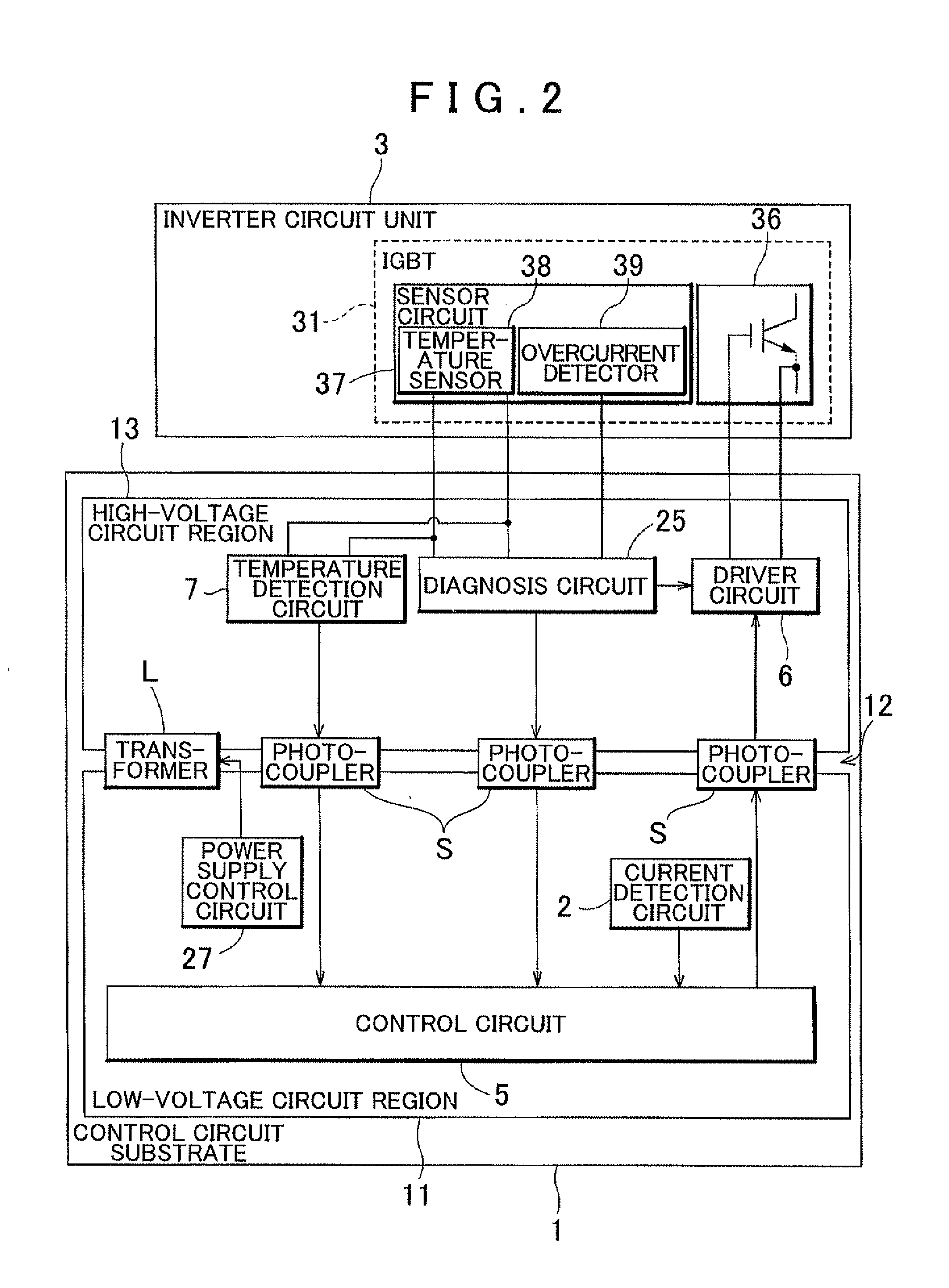
[0014]The control circuit substrate of the inverter device according to a fifth aspect of the present invention may include a logical operation circuit that controls the inverter circuit, and a
noise suppression filter may be provided at least right before the logical operation circuit on a
signal line that transmits a detection result of the current detection circuit to the logical operation circuit. The control circuit substrate is placed parallel to the inverter circuit unit. The inverter circuit unit operates at a higher voltage than the control circuit, and thus a larger amount of current flows in the inverter circuit unit. The high-voltage circuit region that operates at a higher voltage than the control circuit is also formed in the control circuit substrate. Thus, the circuits that are placed in the low-voltage circuit region, such as the control circuit, are in an environment in which the circuits tend to receive
noise of a
high energy level. The detection result of the current detection circuit is also affected by such
noise on the
transmission line. However, the noise is suppressed by providing the
noise suppression filter right before the logical operation circuit that controls the inverter circuit based on the detection result of the current detection circuit. Thus, the logical operation circuit can control the inverter circuit based on an accurate detection result.

