Print head module

a printing head and module technology, applied in the direction of dyeing process, manufacturing tools, inking apparatus, etc., can solve the problems of high capital cost of printing system, large volume of product to be deposited, low flexibility and lack of redundancy in such a printing system, etc., to reduce the calibration required at set-up, reduce the effect of significant calibration requirements and eliminating possible variations in deposition

Active Publication Date: 2014-01-30
TEN CATE ADVANCED TEXTILES BV
View PDF0 Cites 28 Cited by
  • Summary
  • Abstract
  • Description
  • Claims
  • Application Information

AI Technical Summary

Benefits of technology

[0020]The present invention seeks to address at least some of these difficulties by providing a print head module for depositing a substance onto a substrate, the print head module having a transport axis and a traverse axis and comprising first and second print heads having nozzles for depositing the substance, the first and second print heads being staggered with respect to one another along the transport axis and offset from one another along the traverse axis to form an elongate compound head having a length greater than a length of either the first or the second print head, whereby the first and second print heads overlap one another along the transport axis, providing nozzle redundancy and allowing deposition onto the substrate at different swathe angles with respect to the traverse axis, of contiguous first and second swathes of the substance, from the nozzles of the respective first and second print heads. By providing a relatively broad compound swathe from a single carriage that is uniform in both forward and reverse diagonal passes, diagonal printing can take place efficiently even across wide textiles. No alignment and synchronisation between a pair of carriages is required. This can reduce significantly the calibration required at set-up and can eliminate possible variations in deposition along the substrate transport direction. Preferably, the resulting compound head will have an operational length in the transport direction of at least 0.2 m, preferably at least 0.3 m and even as much as 0.8 m. Each of the individual print heads may have an active length significantly shorter than this. The compound head as described above may be relatively compact compared to existing designs and for the same number of nozzles can occupy less than half the length in the transport direction compared with a comb arrangement operating over two beams as described in WO2009 / 056641.

Problems solved by technology

A characteristic of these processes is often that they require considerable volumes of product to be deposited across the whole textile surface.
Fixed array systems have a number of drawbacks, mainly related to the low flexibility and lack of redundancy in such a printing system.
When printing onto a wide substrate with a fixed array system, a large number of print heads are required to straddle the width of the substrate, leading to a high capital cost for the printing system.
If the required substrate speed is below the maximum speed of the print head (e.g. due to other slower processes), then this extra system capacity cannot be usefully exploited and is wasted i.e. at anything below maximum speed, the printing system is making inefficient use of the print heads present.
The resolution across the substrate width is fixed by the position of the print head nozzles and cannot therefore be readily varied.
This is often a relatively complex operation and the downtime associated therewith can be costly.
In the event that a nozzle fails during printing, a single vertical line appears on the substrate, which is a particularly visible mode of failure and represents a complete 100% failure to deposit material in the localized area.
Printing a continuous image also requires a complex continuous data handling system.
This situation can be avoided by using dynamic memory handling where data is fed into memory as fast as it is fed out to the print heads but this requires a significantly more complicated memory management system.
It is however not generally possible to locate two heads next to one another without leaving a gap between.
In these arrangements, printing takes place in scan and step mode and further overlap would lead to inefficient use of the print heads.
Scan and step systems also have a number of drawbacks, mainly focused on the low productivity and the stepping nature of the substrate motion.
In particular, the stepping of the substrate means that such a system has poor compatibility when used as a component or process within a continuous production line.
The time taken to increment or step the substrate cannot be used for printing and limits productivity.
The loss of efficiency due to acceleration and deceleration of the print head is thereby reduced although operation still takes place in scan and step mode.
All of these drawbacks have hitherto made continuous, high-speed and highly uniform deposition onto wide substrates difficult to achieve.
In particular, the reliability of print heads for such operations is still far from optimal.
Nevertheless, the maintenance time comes at the expense of intermittent motion of the substrate.
This can be a cause of additional indexing faults and wear in the drive train.
Furthermore, the rapid acceleration of the print cartridge at each traverse is a potential source of mechanical failure and a design limitation.
In an array configuration, regular maintenance opportunities are not available.
In particular, when printing on both the forward and reverse passes, the print head addresses only unprinted areas of the paper, leading to inefficient nozzle usage.
Furthermore, the document fails to address the need for enhanced head length for printing wide swathes onto large format substrates.
Print head modules having heads arranged in comb arrangement as mentioned above may work well in a scan and step mode but are not directly suitable for operation in a diagonal manner in two passes.
While this arrangement has been found to operate in a satisfactory manner, the setting up thereof is difficult and variations in transport speed or other print parameters can require recalibration.
Any motion of the substrate with respect to the transport belt between the first and second carriages can be catastrophic to the result.
These and other difficulties become more significant as the substrate width and transport speed increase.

Method used


Image

  • Print head module
  • Print head module
  • Print head module

Examples


Embodiment Construction

[0065]The following is a description of certain embodiments of the invention, given by way of example only and with reference to the drawings.

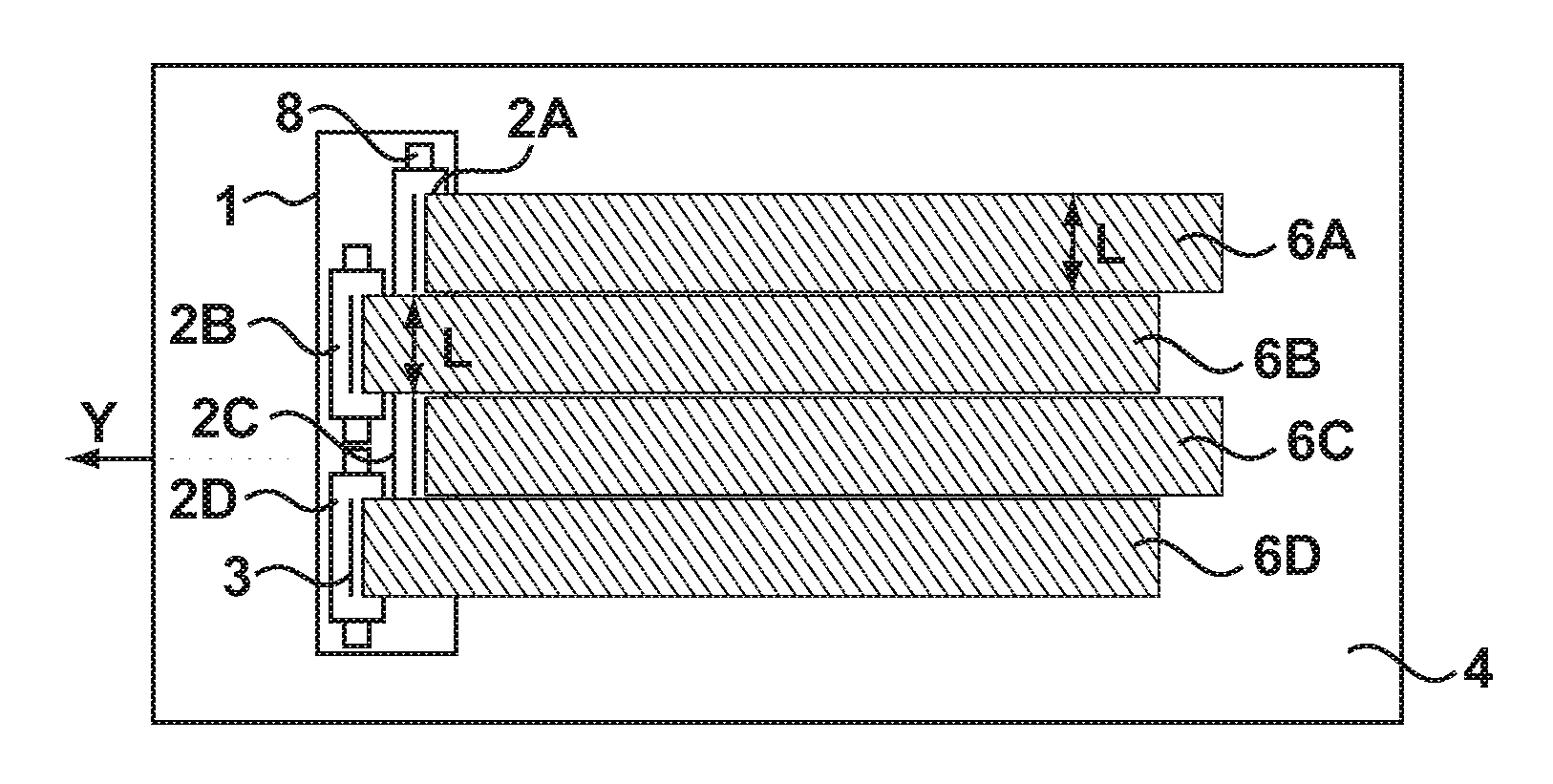
[0066]Referring to FIG. 1, a conventional print head module 1 is shown for printing broad swathes in a scan and step system. The module 1 comprises four heads 2A-D arranged in a staggered fashion in two parallel rows. Each head 2A-D has a plurality of dispensing nozzles 3 arranged in a line. The module 1 may be mounted to a carriage (not shown) for movement in a direction Y across a substrate 4 to deposit four swathes 6A-D. The spacing L between heads 2A and 2C corresponds to the length of head 2B such that swathe 6B precisely spans the gap between the swathes 6A and 6C. It is noted that L represents the active length of the head 2B over which the nozzles 3 are distributed. The physical head is actually longer than L due to the presence of fixation elements 8. In fact, it is the fixation elements 8 and the edge regions of the heads 2A-D that p...


PUM

PropertyMeasurementUnit
widthaaaaaaaaaa
widthaaaaaaaaaa
widthaaaaaaaaaa

Abstract

A print head module (20) for depositing a substance has an axis and a plurality of print heads (22) provided with nozzles (23). The heads are distributed along the axis to form an elongate compound head having nozzle redundancy by arranging the heads in partially overlapping relation to one another. This allows deposition of the substance from the nozzles in uniform swathes having different angles transverse to the axis.

Description

BACKGROUND OF THE INVENTION[0001]1. Field of the Invention[0002]The invention relates generally to a print head module for the deposition of a substance onto a substrate using printing techniques and the like. The invention further relates to a device for producing such a print head module and to procedures for performing deposition in a continuous process, in particular in the fields of textile printing and finishing.[0003]2. Description of the Related Art[0004]Systems for inkjet printing of images and text onto a substrate are generally known. Many such systems are adapted to desktop or office application and are well suited for performing printing onto A3 or A4 sized paper or the like. For wider substrates, more specialized machinery is required, in particular when high speed and high throughput are important. For such applications, inkjet printing techniques may be used as well as lithographic and conventional printing techniques.[0005]For textiles, inkjet printing techniques ha...

Claims


Application Information

Patent Timeline
Patent Type & Authority Applications(United States)
IPC IPC(8): B41J2/115B41J2/16
CPCB41J2/16B41J2/115B41J2/15B41J2/2132B41J3/4078B41J11/0015B41J2202/19B41J2202/20D06P5/30B41J25/001B41J25/34B41J19/16Y10T29/53961B41J2/145B41J3/543B41J3/407
Inventor HUDD, ALANKOELE, GERRITFOX, JAMES E.WALLACE, PAUL
Owner TEN CATE ADVANCED TEXTILES BV
Why Eureka
Try Eureka