Eureka AIR delivers breakthrough ideas for toughest innovation challenges, trusted by R&D personnel around the world.

Assembly type multifunctional microphone array frame device

A microphone array, multi-functional technology, applied in the direction of the transducer shell/cabinet/bracket, etc., can solve the problems that cannot meet the requirements of the microphone acoustic test, the height of the tripod or the support is limited, and the versatility of the array frame is not strong. Achieve the effect of reducing preparation time, facilitating transportation and assembly, and avoiding space waste

Inactive Publication Date: 2019-04-16
LOW SPEED AERODYNAMIC INST OF CHINESE AERODYNAMIC RES & DEV CENT
View PDF9 Cites 4 Cited by
  • Summary
  • Abstract
  • Description
  • Claims
  • Application Information

AI Technical Summary

Problems solved by technology

One is to install the microphone on a tripod or support, but the height of the tripod or support is usually limited (about 2 meters) and only a small number of microphones can be installed, which cannot meet the needs of large-scale wind tunnels and multi-channel (tens to hundreds of) ) Microphone Acoustic Test Requirements
The second is to design and weld a dedicated array rack according to the requirements of the test items and test settings, but this array rack is not very versatile—the array racks are different for different test items or settings, and after the test is completed, it can only be discarded or discarded. Takes up a lot of space for storage

Method used


Image

  • Assembly type multifunctional microphone array frame device
  • Assembly type multifunctional microphone array frame device
  • Assembly type multifunctional microphone array frame device

Examples


Embodiment 1

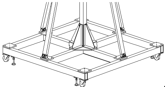
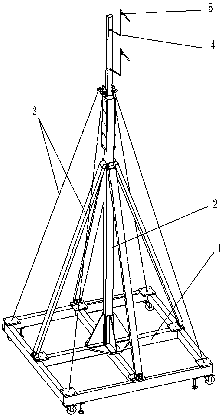
[0029] Such as image 3 As shown, it is a schematic diagram of a single-piece assembled multifunctional microphone array frame after assembly. Its structure is simple and easy to disassemble. Seat 5 etc. are assembled.

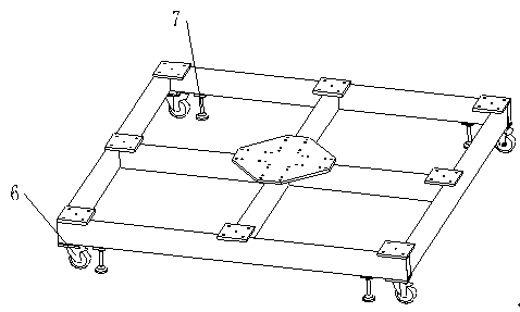
[0030] Such as figure 1 As shown, the movable base 1 of the present invention is a frame structure, which is welded by four steel pipes in the outer frame and four steel pipes in the inner frame. There is a platform in the middle of the four steel pipes in the inner frame, and the pre-drilled holes on the platform are convenient for connecting the columns. There is a small platform above the four corners where the outer frame and the inner frame intersect, and a hole is pre-punched in the middle of the platform to connect with the reinforcement auxiliary device. A small platform is also respectively arranged above the four corners of the movable base 1, and holes are pre-punched in the middle of the platform to connect spare eyebolts. The bottom of the fou...

Embodiment 2

[0037] Such as Figure 4 As shown, taking the 30-channel far-field microphone array rack device as an example, the implementation process of the present invention is given.

[0038] According to the requirements of the test project and test settings, the overall length of the microphone array frame is 12 meters, and the height is 11 meters. The microphones are arranged in three rows, with 10 channels of microphones in each row, and all microphones must point to the same given position. In order to achieve the above purpose and ensure the stability of the entire array rack, 4 pieces such as image 3 The assembled device shown (in which the column 2 includes two sections of aluminum profiles of different thicknesses) is assembled with 6 aluminum profile brackets, 30 array struts 4 and 30 universal adjustment seats 5 .

[0039] After the processing is completed, the single-piece movable base 1 is as follows figure 1 As shown as a whole, other aluminum profiles, array struts 4 a...


PUM


Abstract

The invention discloses an assembly type multifunctional microphone array frame device. The device comprises bases and supporting frames set on the bases. Each supporting frame comprises a supportingvertical post and a plurality of array units which are connected with the supporting vertical post. Each array unit is formed by splicing a plurality of supporting rods with the same structure. The supporting rods and the supporting vertical posts are the same in structure. Sliding slots for positioning and fixing are set on each face. Struts for fixing microphones are set in the sliding slots. Locations of the microphones can be adjusted through sliding of the struts. Compared with a conventional array frame, the assembly type multifunctional microphone array frame device has the major advantage of disassembly. Huge array frames can be stored easily, so relatively high space waste is avoided. Proximate matters are taken as major components of the array frames, so the array frames can be randomly combined, the same supporting frames can be combined into the array frames satisfying different shape requirements, and different wind tunnel tests are satisfied.

Description

technical field [0001] The invention belongs to the field of noise testing, in particular to an assembled multifunctional microphone array frame device. Background technique [0002] In addition to the wind tunnel itself, the wind tunnel test equipment mainly includes models, support devices and test systems, which constitute the three basic elements of implementing wind tunnel tests. During the wind tunnel test, the model is installed on the supporting device, blown in the wind tunnel, and the test data of the model's aerodynamic force and aerodynamic noise are obtained through the test system (balance, pressure measuring valve, microphone, etc.). [0003] During the noise test, the microphone (commonly known as the microphone) is an essential component of the test system. In order to fix the microphone at the specified position in the test site (wind tunnel or field), there are traditionally two types of methods. One is to install the microphone on a tripod or support, b...

Claims


Application Information

Patent Timeline
Patent Type & Authority Applications(China)
IPC IPC(8): H04R1/02
CPCH04R1/02
Inventor 王勇李征初陈正武赵昱黄奔唐道锋梁勇卢翔宇田昊张俊龙
Owner LOW SPEED AERODYNAMIC INST OF CHINESE AERODYNAMIC RES & DEV CENT
Why Eureka
Eureka Blog
Learn More