LED stroboflash-free control circuit

A control circuit and flicker-free technology, which is applied in the field of LED flicker-free control circuits, can solve problems such as power grid interference, audio noise, flicker, etc.

Inactive Publication Date: 2019-04-16
江西晶磊科技有限公司
View PDF4 Cites 1 Cited by
  • Summary
  • Abstract
  • Description
  • Claims
  • Application Information

AI Technical Summary

Problems solved by technology

It is precisely because the sine wave is cut and the waveform is destroyed, which will cause interference to the power grid and other problems, the LED drive power will produce audio noise and flicker, res

Method used


Image

  • LED stroboflash-free control circuit
  • LED stroboflash-free control circuit
  • LED stroboflash-free control circuit

Examples


Embodiment Construction

[0015] The invention provides a method for LED non-flicker control circuit. In order to make the object, technical solution and effect of the present invention more clear and definite, the present invention will be further described in detail below with reference to the accompanying drawings. It should be understood that the specific embodiments described here are only used to explain the present invention, not to limit the present invention.

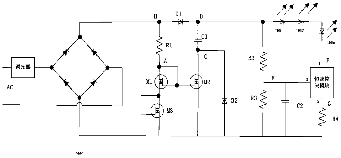
[0016] In the prior art, because the LED light source has current only when the voltage is greater than the conduction voltage, no current flows when the voltage at both ends is less than the conduction voltage; the dimming mechanism of the thyristor dimmer, the sine wave is cut, and the waveform Damage will cause interference to the power grid, and audio noise and flicker will be generated for the LED drive power supply, resulting in the flickering problem of the LED lamp and reducing the power factor (PF) value of the circuit.

[001...


PUM


Abstract

The invention provides an LED stroboflash-free control circuit. A current mirror composed of M1 and M2 realizes current mirror image. A piezoelectric tube M3 improves a grid control voltage of the current mirror and reduces the mirror image proportion of the current mirror. A current-limiting resistor limits a current on an On circuit. An anti-current-backflow diode D1 prevents the current from flowing backwards into the current mirror. A charging capacitor C1 is used for storing a voltage, and a follow current loop D2 continuously provides a current for an LED lamp. The current mirrored by the current mirror and the current generated by the follow current loop ensure that the controllable gauge dimmer maintains the On state of the circuit, thereby reducing the flicker index. Meanwhile, the circuit also can guarantee that the input current and the input voltage have the same phase, and guarantees that a high power factor exists. The circuit has the advantages of simple circuit structure, obvious stroboscopic effect removal, small chip area, low cost and high power factor.

Description

technical field [0001] The invention relates to the field of LED lamps, in particular to an LED flicker-free control circuit. Background technique [0002] The emergence of LED lamps greatly reduces the power required for lighting. LED lamps with the same wattage require only 1 / 10 of the power required by incandescent lamps. At the same time, LED lamps have the advantages of long life, environmental protection, and maintenance-free, while SCR Dimmers are widely used in traditional lighting markets such as incandescent lamps. They are simple and easy to be used by consumers and conform to people's usage habits. Compatible with TRIAC dimmers. [0003] The dimming mechanism of the thyristor dimmer uses the phase control method to realize voltage regulation or dimming. At a certain moment after the sine wave alternating current crosses zero, a trigger pulse is added to the control electrode of the thyristor to make the thyristor conduct, and this conduction will be maintained ...

Claims


Application Information

Patent Timeline
IPC IPC(8): H05B33/08H05B44/00
CPCH05B45/00
Inventor 李桂宏王建国
Owner 江西晶磊科技有限公司
Why Eureka
Try Eureka