Method and device for changing dynamic behavior of loom back beam

A backrest beam, loom technology, applied in looms, textiles, papermaking, textiles, etc., can solve problems such as inappropriateness and unreasonableness

Inactive Publication Date: 2021-06-25
LINDAUER DORNIER GMBH
View PDF8 Cites 0 Cited by
  • Summary
  • Abstract
  • Description
  • Claims
  • Application Information

AI Technical Summary

Problems solved by technology

[0007] In using this back beam arrangement, it has been found that the smallest possible warp load is unreasonable or inappropriate for all weaving conditions or requirements and for all fabrics

Method used


Image

  • Method and device for changing dynamic behavior of loom back beam
  • Method and device for changing dynamic behavior of loom back beam

Examples


Embodiment Construction

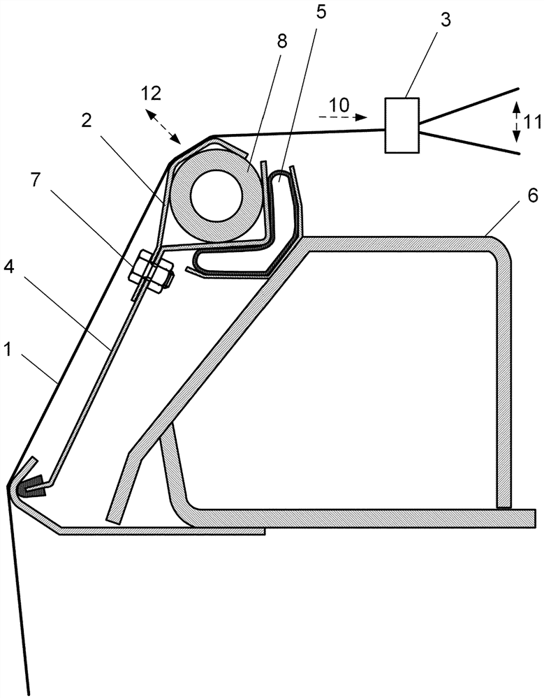
[0034] figure 1 An embodiment of the weaving machine according to the invention is shown in a sectional view, where the viewing direction is in the weft direction onto the rear of the machine. Starting from a not shown warp beam, the warp thread 1 is guided around a deflection element 2 and from there—via a device for monitoring the warp thread 3—is fed to the front of the weaving machine and to the shed for shedding and reed beat-up. element.

[0035] In the present example, the deflection element 2 is embodied as a bent sheet metal. It is now screwed together with a support element 4 in the form of a bent sheet metal, to which an air bellows 5 is attached at one end, while the other end is supported or supported at an articulation point in the frame of the weaving machine 6 .

[0036] Here, the air bellows 5 forms a spring element on which the deflection element 2 is connected to the weaving machine in such a way that when a force is applied or imposed on the deflection el...


PUM


Abstract

The invention relates to a method for changing the dynamic behavior of a back beam of a weaving machine and a weaving machine with a back beam, wherein the back beam comprises at least one deflecting element (2) for deflecting a warp thread (1), wherein the deflecting element ( 2) connected to the loom via one or more spring elements in such a way that when a force is applied to the deflection element (2) via the warp thread (1), inertial and spring forces become effective on the deflection element ( 2). The effective inertial mass on the deflection element (2) is varied in order to adapt the dynamic behavior of the back beam to changing weaving conditions, replacement, removal of parts of the deflection element (2) or parts connected to the deflection element (2) or supplement.

Description

technical field [0001] The invention relates to a method for changing the dynamic behavior of a backrest beam of a weaving machine, and a weaving machine with a backrest suitable for carrying out the method. Background technique [0002] With regard to weaving machines, devices for deflecting warp threads are known in the prior art, known as back beams, back rollers or whip rollers. [0003] Such a device is shown, for example, in DE 10 2006 061 376 A1. This relates to backrest beams for weaving machines, in which the upward warp thread movement is compensated or equalized by thread deflection elements which are pivotably arranged on mass-optimized leaf springs. [0004] In this respect, in the prior art, the mentioned mass optimization aims at configuring or embodying the dynamic behavior of the back beam at high weaving speeds in such a way that the smallest possible warp tensions are produced. This is achieved by the small inertial mass of the threaded deflection elemen...

Claims


Application Information

Patent Timeline
Patent Type & Authority Patents(China)
IPC IPC(8): D03D49/12
CPCD03D49/12
Inventor M.菲比希M.吉伦D.奥伯迈尔
Owner LINDAUER DORNIER GMBH
Why Eureka
Try Eureka