Hand gripper

A technology of gripping device and connecting tube, applied in the medical field, can solve the problems of people persevering and unable to control the strength effectively, and achieve the effects of enhancing comfort, exercising hand strength, and enhancing blood circulation

Active Publication Date: 2019-04-19
SHAOXING KEQIAO JINCE INTELLIGENT TECH CO LTD
View PDF6 Cites 8 Cited by
  • Summary
  • Abstract
  • Description
  • Claims
  • Application Information

AI Technical Summary

Problems solved by technology

[0003] In order to overcome the shortcomings of ordinary grippers that are difficult for people to persist and cannot effectively control the strength, the technical problem to be solved is: to provide a gripper that can strengthen people's willingness to exercise and can effectively control the strength of exercise

Method used


Image

  • Hand gripper
  • Hand gripper
  • Hand gripper

Examples


Embodiment 1

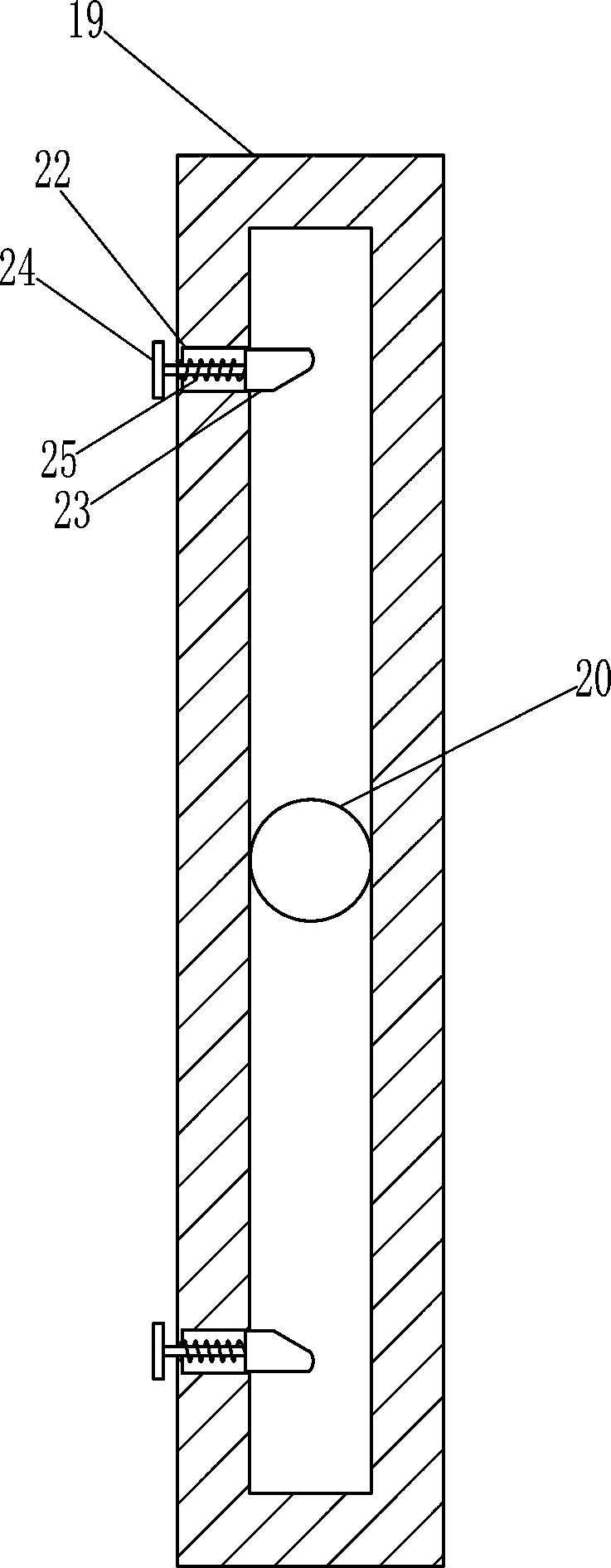
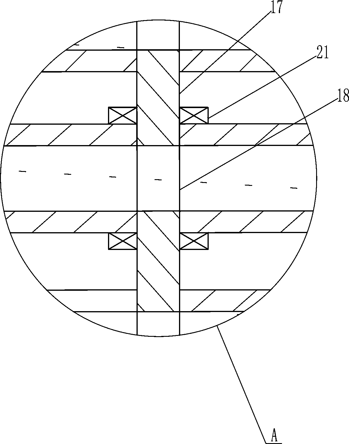
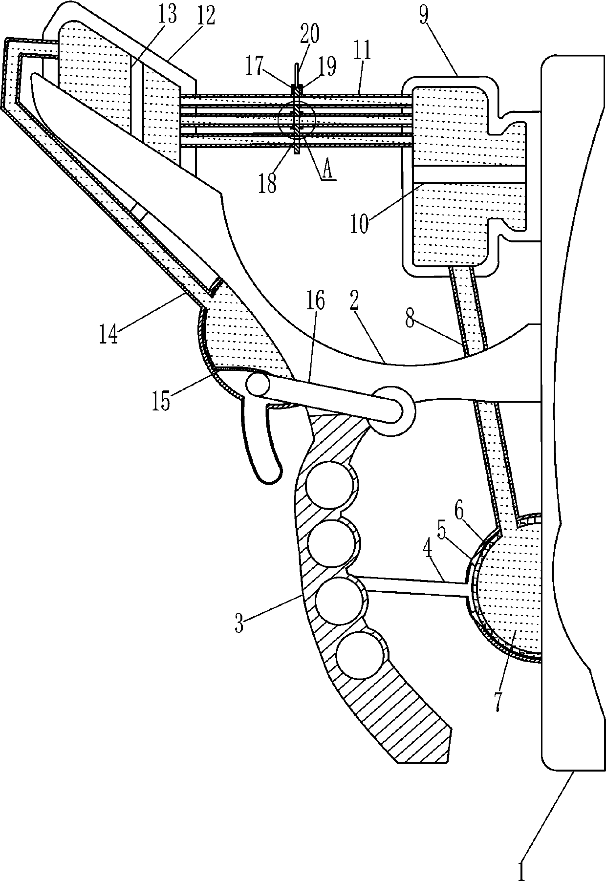
[0018] a grip, such as Figure 1-4 As shown, it includes bottom plate 1, support plate 2, grip rod 3, pressure rod 4, soft bag 6, water 7, lower connecting pipe 8, right cylinder body 9, right piston 10, upper connecting pipe 11, left cylinder body 12 , the left piston 13, the left connecting pipe 14, the liquid bag 15 and the connecting rod 16; There is a pressure rod 4, the lower left side of the bottom plate 1 is connected with a lower connecting pipe 8, the lower left side of the lower connecting pipe 8 has an opening 5, the lower part of the lower connecting pipe 8 is provided with a soft bag 6, the right end of the pressing rod 4 passes through the opening 5 and In contact with the left side of the soft bag 6, the top of the lower connecting pipe 8 is equipped with a right cylinder 9, the right side of the right cylinder 9 is connected to the upper left side of the bottom plate 1, the right cylinder 9 communicates with the lower connecting pipe 8, and the inside of the r...

Embodiment 2

[0020] a grip, such as Figure 1-4 As shown, it includes bottom plate 1, support plate 2, grip rod 3, pressure rod 4, soft bag 6, water 7, lower connecting pipe 8, right cylinder body 9, right piston 10, upper connecting pipe 11, left cylinder body 12 , the left piston 13, the left connecting pipe 14, the liquid bag 15 and the connecting rod 16; There is a pressure rod 4, the lower left side of the bottom plate 1 is connected with a lower connecting pipe 8, the lower left side of the lower connecting pipe 8 has an opening 5, the lower part of the lower connecting pipe 8 is provided with a soft bag 6, the right end of the pressing rod 4 passes through the opening 5 and In contact with the left side of the soft bag 6, the top of the lower connecting pipe 8 is equipped with a right cylinder 9, the right side of the right cylinder 9 is connected to the upper left side of the bottom plate 1, the right cylinder 9 communicates with the lower connecting pipe 8, and the inside of the r...

Embodiment 3

[0023] a grip, such as Figure 1-4 As shown, it includes bottom plate 1, support plate 2, grip rod 3, pressure rod 4, soft bag 6, water 7, lower connecting pipe 8, right cylinder body 9, right piston 10, upper connecting pipe 11, left cylinder body 12 , the left piston 13, the left connecting pipe 14, the liquid bag 15 and the connecting rod 16; There is a pressure rod 4, the lower left side of the bottom plate 1 is connected with a lower connecting pipe 8, the lower left side of the lower connecting pipe 8 has an opening 5, the lower part of the lower connecting pipe 8 is provided with a soft bag 6, the right end of the pressing rod 4 passes through the opening 5 and In contact with the left side of the soft bag 6, the top of the lower connecting pipe 8 is equipped with a right cylinder 9, the right side of the right cylinder 9 is connected to the upper left side of the bottom plate 1, the right cylinder 9 communicates with the lower connecting pipe 8, and the inside of the r...


PUM


Abstract

The invention relates to the field of medical treatment, in particular to a hand gripper and aims to provide a hand gripper capable of strengthening exercising willing of people and effectively controlling exercising intensity to solve technical problems. The technical scheme includes that the hand gripper comprises a bottom plate, a supporting plate, a holding rod, a pressure rod, a soft bag, water, a lower connection pipe, a right cylinder body, a right piston, an upper connection pipe, a left cylinder body, a left piston and the like. The supporting plate is connected to the middle of the left side of the bottom plate, the holding rod is rotationally connected to the right side of the bottom of the supporting plate, the pressure rod is connected to the middle of the right side of the holding rod, the lower connection pipe is connected to the lower portion of the left side of the bottom plate, the lower portion of the left side of the lower connection pipe is provided with an opening, and the soft bag is arranged on the inner lower portion of the lower connection pipe. A patient can repeatedly push the pressure rod side to side to enable reciprocating flowing of water, hand strength of the patient can be improved, blood circulation is enhanced, and rehabilitation of the patient is benefited. Comfort in finger motion of the patient can be improved by water, the willing of thepatient using the hand gripper to exercise can be strengthened, and the patient is enabled to keep going.

Description

technical field [0001] The invention relates to the medical field, in particular to a force grip. Background technique [0002] When people cause hand muscle or soft tissue damage due to some accidents, they often need to use the restorer to exercise hand strength and enhance blood circulation during rehabilitation training under the guidance of doctors, so that finger flexibility can be gradually improved. Grip is a common recovery device. People have a long recovery period after surgery for hand injuries. At this time, use a grip for recovery, while ordinary grips use springs for exercise, so the exercise is not only ineffective , it is difficult to make people stick to it, and it is impossible to effectively control the intensity. If the exercise intensity is too high, it is very easy to cause muscle damage again. Contents of the invention [0003] In order to overcome the shortcomings of ordinary grippers that make it difficult for people to persevere and effectively ...

Claims


Application Information

Patent Timeline
Patent Type & Authority Applications(China)
IPC IPC(8): A63B23/16A63B21/008
CPCA63B21/008A63B23/16
Inventor 刘华溢
Owner SHAOXING KEQIAO JINCE INTELLIGENT TECH CO LTD
Why Eureka
Try Eureka