
Plane truss production line

A flat truss, production line technology, applied in the direction of manufacturing tools, metal processing, metal processing equipment, etc., can solve the problems of easily broken steel bars, difficult to grasp the angle, time-consuming and labor-intensive, etc., to achieve automatic processing, beautiful fixation, overall strong effect

Pending Publication Date: 2019-04-19
浙江亿洲机械科技有限公司
View PDF0 Cites 6 Cited by
  • Summary
  • Abstract
  • Description
  • Claims
  • Application Information

AI Technical Summary

Problems solved by technology

There are various production methods for this type of planar truss, such as splicing and welding several horizontal steel bars, but it is time-consuming and labor-intensive, and cannot be mass-produced quickly; there is a method of bending the steel bars in the middle and welding longitudinal steel bars at both ends. The flat truss has good integrity and is more stable, but the existing equipment cannot continuously bend the steel bars, and the non-continuously bent steel bars are not easy to grasp the angle, the appearance is not beautiful, and the non-continuously bent steel bars are easy to break the steel bars

Method used


Image

  • Plane truss production line
  • Plane truss production line
  • Plane truss production line

Examples


Embodiment Construction

[0040] In order to make the above objects, features and advantages of the present invention more comprehensible, the specific implementation manners of the present invention will be described in detail below in conjunction with the accompanying drawings.

[0041] Example.

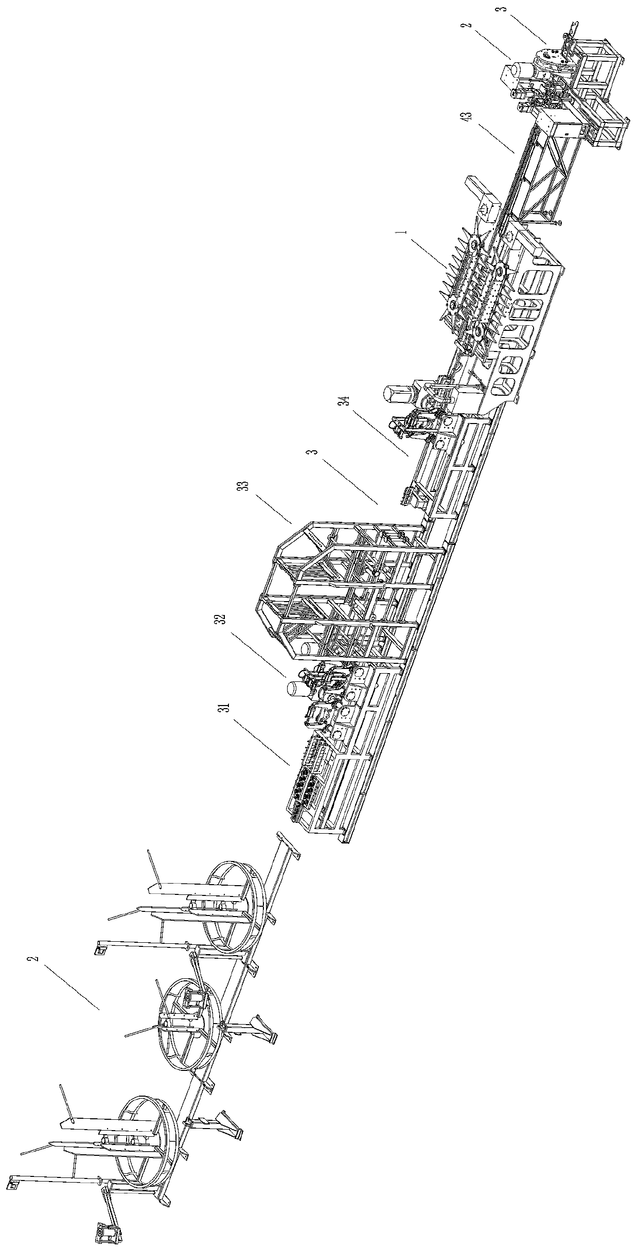
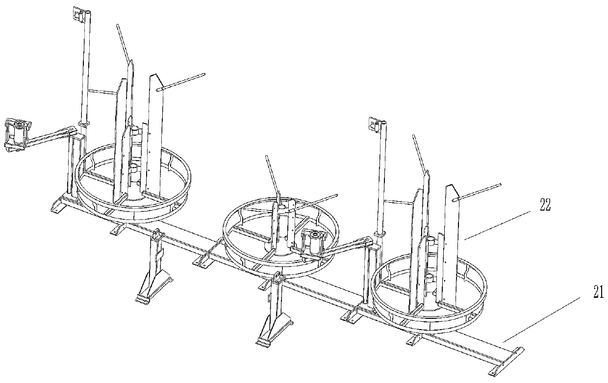
[0042] Such as Figure 1-4 As shown, this embodiment includes a pay-off device 2 and a straightening and rolling device 3 , a folding device 1 , a welding device 4 and a shearing device 5 connected in sequence. The pay-off device 2 is used to place the steel bar roll and derive three steel bars used as a welded plane truss from the steel wire roll. The pay-off device 2 includes a pay-off base 21, three placement racks 22 installed on the pay-out base 21, and the placement rack 22 is rotatably connected with the pay-off base 21, and the placement frame 22 is used for winding the reinforcing bar that has not been processed through straightening. Wherein, because the required diameter of the reinforcing bar ...


PUM


Abstract

The invention belongs to the field of plane truss production, and particularly relates to a plane truss production line. The plane truss production line comprises a placing device, a straightening roller pressing device, a waving device, a welding device and a shearing device, wherein the waving device comprises a waving base, a waving drive, a side steel bar guide pipe, a fixed waving device anda movable waving device, and the fixed waving device comprises a first rotating shaft and a first crawler belt, triangular plates are fixed on the outer side of the first crawler belt, and the movablewaving device comprises a sliding guide rail, a sliding base, a second rotary shaft and a second crawler belt, triangular plates are fixed on the outer side of the second crawler belt, and the wavingdrive is connected with the first rotary shaft and the second rotary shaft; the welding device comprises a welding frame and welding heads; the shearing device comprises a shearing base and a cutterframe, and a cutter rotating shaft is arranged on the cutter frame, a cutter connecting part sleeves the cutter rotating shaft, and a shearing cutter is hinged to the lower part of the cutter connecting part. According to the plane truss production line, the steel bar can be processed into the plane truss, the processing process is automatic, the efficiency is high, and the method is suitable forlarge-scale plane truss processing.

Description

technical field [0001] The invention belongs to the field of plane truss production, and in particular relates to a plane truss production line. Background technique [0002] A truss is a structure in which members are connected to each other by hinges at both ends. The truss is composed of straight rods and generally has a plane or space structure of triangular units. The truss members mainly bear axial tension or pressure, so that the strength of the material can be fully utilized. When the span is large, it can save materials compared with solid web beams, reduce self-weight and Increase stiffness. The advantage of the truss is that the rods mainly bear tension or pressure, which can give full play to the role of materials, save materials, and reduce structural weight. Commonly used are steel truss, reinforced concrete truss, prestressed concrete truss, wooden truss, steel and wood composite truss, steel and concrete composite truss. Trusses are divided into planar tru...

Claims


Application Information

Patent Timeline
Patent Type & Authority Applications(China)
IPC IPC(8): B21F1/02B21F15/08B21F11/00B21F1/04B21F23/00B21C51/00
CPCB21C51/00B21F1/02B21F1/04B21F11/00B21F15/08B21F23/00
Inventor 陈增光姜飞贵李志平朱家荣
Owner 浙江亿洲机械科技有限公司
Learn More