Gear case gear shaft pin head laser welding feeding and discharging device

A laser welding and gear shaft technology, applied in the field of mechanical transmission, can solve the problems of difficult to ensure product quality, weak welding, loss of workpiece cost, etc., to achieve the effect of improving welding quality and welding efficiency, and preventing unstable installation.

Inactive Publication Date: 2019-04-19
李慧
View PDF8 Cites 2 Cited by
  • Summary
  • Abstract
  • Description
  • Claims
  • Application Information

AI Technical Summary

Problems solved by technology

[0002] The gear box is an important part widely used in mechanical transmission, especially the gear shaft, which is a common part on the reducer, can play a very critical role. At present, in the technology of welding the pin head and the cover plate, it is done manually by the welder. Laser welding the pin head on the cover plate is very prone to poor welding or welding misalignment in the manual process. After manual processing, the appearance uniformity, consistency, accuracy and other aspects are not good. It is difficult to ensure the quality of the processed products, which has very high technical requirements for workers, and will lose a lot of workpiece costs. This welding method will cause great damage to workers' eyes, and the current labor costs are high and welding efficiency is low. ; while a small number of welding manufacturers use automated equipment for welding, but they all use a single welding method, only welding the pin head and the cover plate, which is far from enough in terms of accuracy requirements, and there is no inspection equipment and adjustment equipment for welding. Adjustment and detection before and after, this will greatly affect the quality of the workpiece after welding, and the current welding processing equipment is unstable and prone to errors, resulting in low calibration of the entire welding

Method used


Image

  • Gear case gear shaft pin head laser welding feeding and discharging device
  • Gear case gear shaft pin head laser welding feeding and discharging device
  • Gear case gear shaft pin head laser welding feeding and discharging device

Examples


Embodiment Construction

[0031] In order to make the present invention more obvious and understandable, the detailed description is as follows in conjunction with the accompanying drawings.

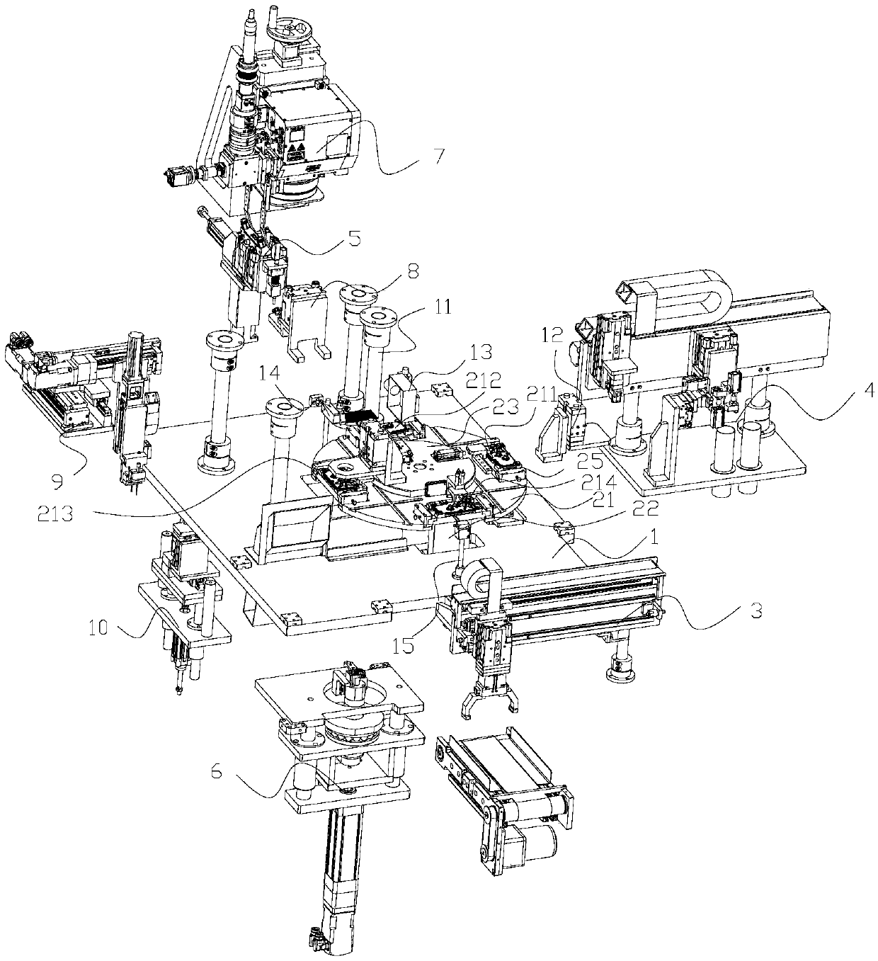
[0032] Such as figure 1 with Figure 11As shown, a gearbox gear shaft laser welding detection equipment, the equipment includes a frame 1, an indexing device, a cover plate loading and unloading device 3, a pin head loading and unloading device 4, an axial gap closed-loop device 5, an axial gap Adjusting device 6 , laser welding device 7 , pin head pressing device 8 , eddy current testing device 9 and axial clearance testing device 10 . The indexing plate device includes an indexing plate 21 , an indexing plate drive module 22 and a fixed plate 23 . The index plate drive module 22 is fixedly arranged on the frame 1, the fixed plate 23 is connected with the index plate drive module 22 through the intermediate transition plate, and the index plate 21 is located at the index plate drive module 22 And between the ...


PUM


Abstract

The invention relates to the technical field of mechanical transmission, in particular to a gear case gear shaft pin head laser welding feeding and discharging device and welding detection equipment.The gear case gear shaft pin head laser welding feeding and discharging device comprises a pin head feeding and discharging module, a pin head middle transition module and a fan tooth tidying module.The pin head feeding and discharging module comprises a pin head feeding and discharging support, a pin head motor support, a pin head motor, a pin head rotation shaft, a first pin head rotation shaftfixing block, a second pin head rotation shaft fixing block, a pin head moving block, a pin head sliding plate, a pin head feeding assembly and a pin head discharging assembly. The pin head feeding assembly is used for pin head conveying and feeding. The pin head discharging assembly is used for disqualified pin head discharging. The pin head middle transition module is used for middle transition. The fan tooth tidying module is used for fan tooth tidying. The gear case gear shaft pin head laser welding feeding and discharging device has the beneficial effects that pin heads can be automatically conveyed to a cover plate; products with the disqualified quality can be subjected to discharging treatment through rotation; the position of fan teeth can be adjusted; and unstability of installation with the pin heads can be prevented.

Description

technical field [0001] The invention relates to the technical field of mechanical transmission, in particular to a laser welding loading and unloading device and welding detection equipment for a gear shaft pin head of a gearbox. Background technique [0002] The gear box is an important part widely used in mechanical transmission, especially the gear shaft, which is a common part on the reducer, can play a very critical role. At present, in the technology of welding the pin head and the cover plate, it is done manually by the welder. Laser welding the pin head on the cover plate is very prone to poor welding or welding misalignment in the manual process. After manual processing, the appearance uniformity, consistency, accuracy and other aspects are not good. It is difficult to ensure the quality of the processed products, which has very high technical requirements for workers, and will lose a lot of workpiece costs. This welding method will cause great damage to workers' ey...

Claims


Application Information

Patent Timeline
IPC IPC(8): B23K26/21B23K26/70
CPCB23K26/21B23K26/702
Inventor 李慧
Owner 李慧
Why Eureka
Try Eureka