Jointed mechanism of electric wheelchair

a jointed mechanism and electric wheelchair technology, applied in the direction of suspensions, pedestrian/occupant safety arrangements, tractors, etc., can solve the problems that the conventional electric wheelchair and the rigidly mounted caster cannot meet people's requirements for stability, and achieve the effect of simple structure and high reliability

Active Publication Date: 2009-04-14
TANG CHENGHUI
View PDF39 Cites 59 Cited by
  • Summary
  • Abstract
  • Description
  • Claims
  • Application Information

AI Technical Summary

Benefits of technology

[0004]To solve the foregoing drawbacks in the prior art, it is an objective of the present invention to provide a jointed mechanism of an electric wheelchair having a simple structure, stable conveyance, and high reliability. The jointed mechanism constructs a four-bar linkage to allow all wheels of the electric wheelchair to always have contact with the ground and automatically adjust the center of gravity to maintain balance, even when the electric wheelchair is climbing a slope or moving on an uneven surface.
[0011]Conclusively, the jointed mechanism of the electric wheelchair according to the present invention constructs a four-bar linkage. The jointed mechanism of the present invention has merits of simple structure, steady conveyance, and high reliability to make the electric wheelchair have contact with the ground with all wheels and adjust the center of gravity to maintain balance automatically at all times, even when the electric wheelchair is climbing a slope or moving on an uneven surface.

Problems solved by technology

In conclusion, the conventional electric wheelchair, with rigidly mounted casters cannot satisfy people's requirements for stability when climbing a slope or traversing uneven terrain.

Method used


Image

  • Jointed mechanism of electric wheelchair
  • Jointed mechanism of electric wheelchair
  • Jointed mechanism of electric wheelchair

Examples


Embodiment Construction

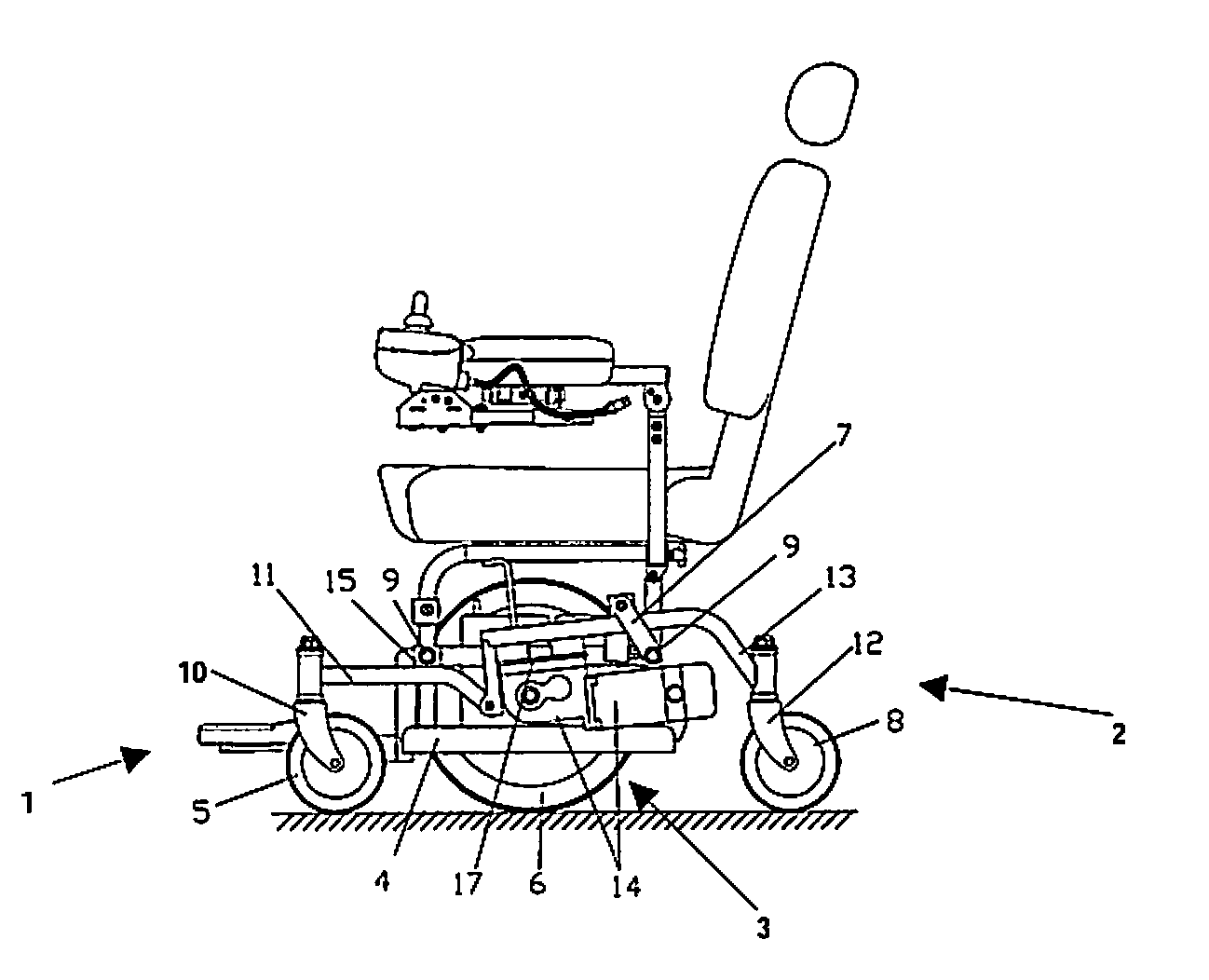
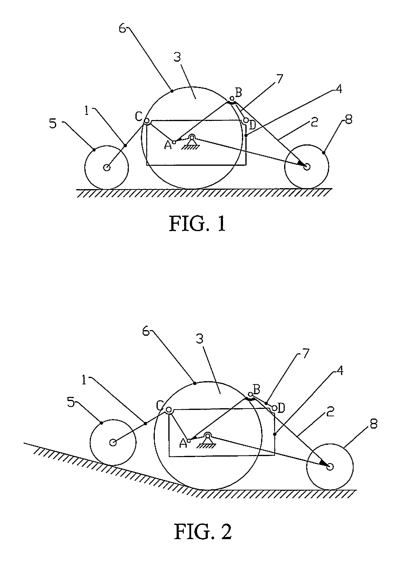
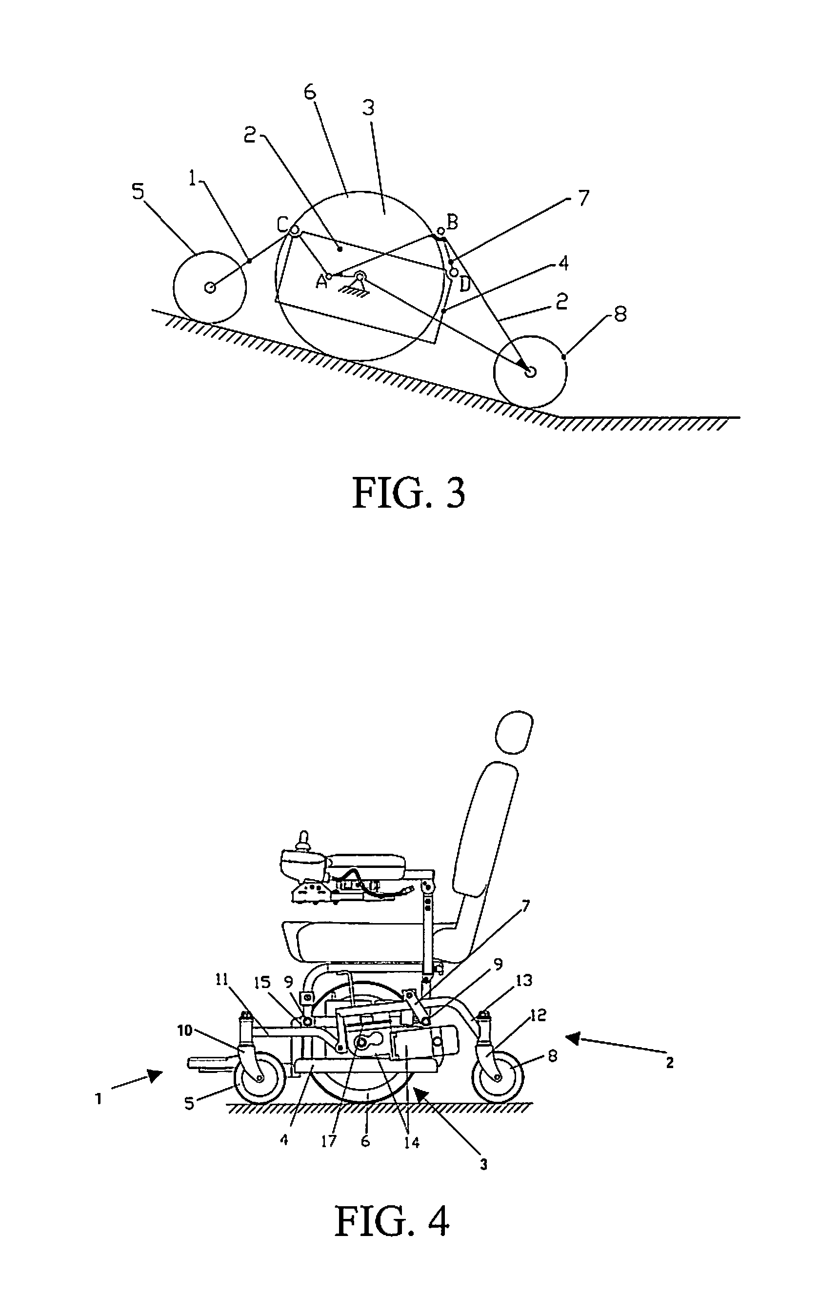
[0020]Please refer to FIGS. 1 to 3, illustrations of the operating principle of an electric wheelchair according to the present invention are shown. The electric wheelchair according to the present invention has a jointed mechanism that provides stability to the electric wheelchair when the electric wheelchair is climbing a slope or on an uneven surface. The jointed mechanism of the electric wheelchair constructs a four-bar linkage, comprising two front caster assemblies 1, two rear caster assemblies 2, two drive wheel assemblies 3, and a main chassis assembly 4. The caster assemblies 1, 2 and the drive wheel assemblies 3 are symmetrically arranged; therefore a detailed description is mentioned below.

[0021]The electric wheelchair is in a condition as shown as in FIG. 1 when the electric wheelchair moves on an even surface. The weight of the main chassis assembly acts evenly on hinges C and D. The gravitational action on the hinge C is transmitted to the front caster anti-tip wheel 5...


PUM


Abstract

A jointed mechanism of an electric wheelchair is disclosed. The jointed mechanism includes symmetrically arranged front caster assemblies, symmetrically arranged rear caster assemblies, drive wheel assemblies, and a main chassis assembly. The front caster assemblies are bushed to the main chassis assembly and the rear caster assemblies respectively. The rear caster assemblies are fixed to the drive wheel assemblies by pivot arm plate assemblies and bushed to the main chassis assembly and the rear caster assemblies to construct a four-bar linkage, which allows the electric wheelchair to always have contact with the ground with all wheels and to adjust the center of gravity to maintain balance automatically, even when the electric wheelchair is climbing a slope or moving on an uneven surface.

Description

FIELD OF THE INVENTION[0001]The present invention generally relates to an electric wheelchair, and more particularly, to a jointed mechanism for front caster assemblies, rear caster assemblies, drive wheel assemblies, and a main chassis assembly of an electric wheelchair.BACKGROUND OF THE INVENTION[0002]Nowadays, a wheelchair is generally employed as a means of transportation for a patient or an aged person who cannot walk by themselves in hospital or for daily life. The electric wheelchair is a very common type of transportation for people who are patients, aged or for any reason cannot walk. The electric wheelchair comprises two front caster assemblies, two drive wheel assemblies, and two rear caster assemblies, pivotally assembled to a main frame, which supports the seat of the electric wheelchair. The front caster assemblies lead the movement and prevent toppling of the electric wheelchair. The drive wheel assemblies connect to a power control system of the wheelchair for drivin...

Claims


Application Information

Patent Timeline
Patent Type & Authority Patents(United States)
IPC IPC(8): B60K1/00
CPCA61G5/043A61G5/06Y10S180/907
Inventor TANG, CHENGHUI
Owner TANG CHENGHUI
Why Eureka
Try Eureka