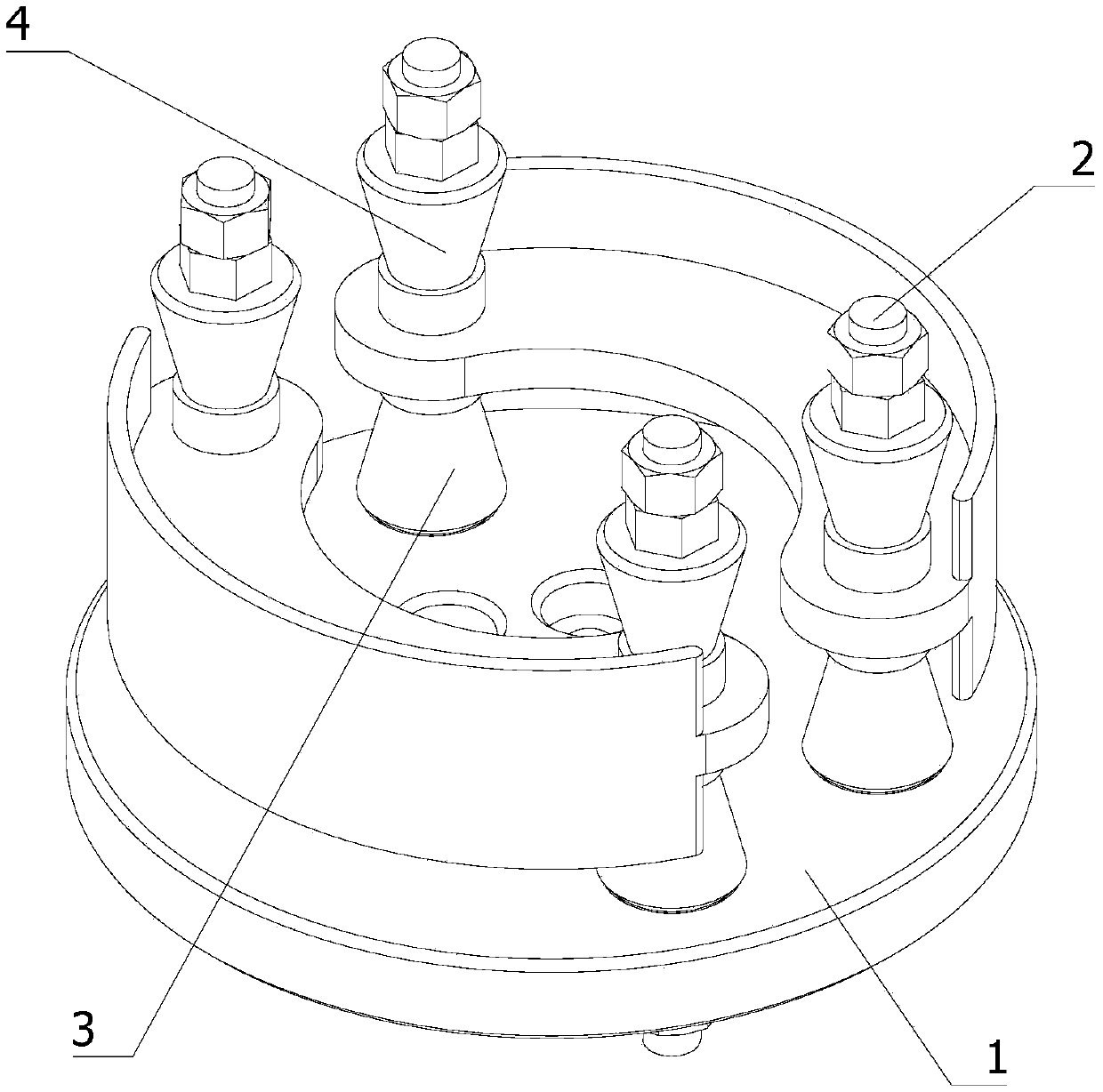
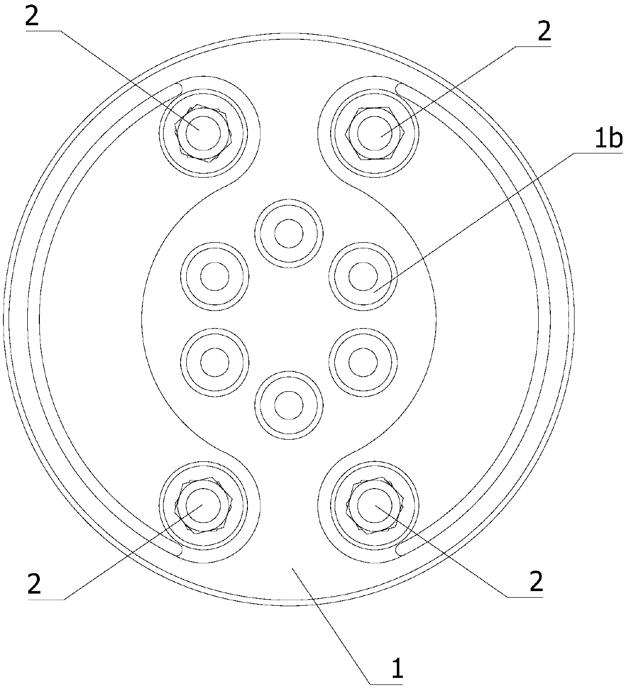
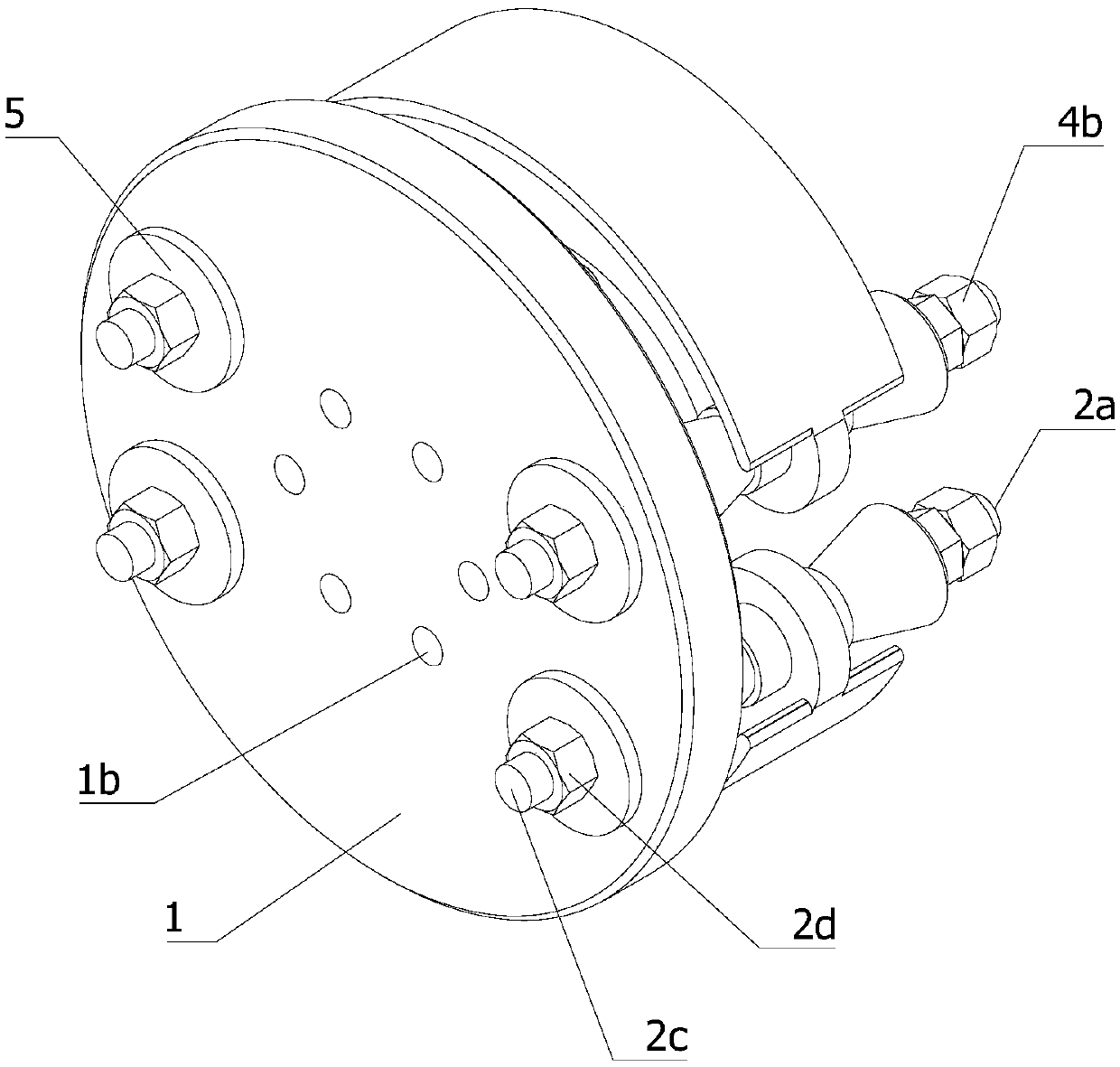
Brake shoe outer circle machining clamp

A brake shoe and fixture technology, which is applied in the direction of manufacturing tools, metal processing equipment, metal processing machinery parts, etc., can solve the problems of reduced machining accuracy and vibration of the outer circular surface

Inactive Publication Date: 2019-04-19
丽水市信裕机械制造有限公司
View PDF1 Cites 2 Cited by
  • Summary
  • Abstract
  • Description
  • Claims
  • Application Information

AI Technical Summary

Problems solved by technology

[0009] Aiming at the deficiencies of the prior art, the present invention provides a clamp for processing the outer circle of brake shoes, which can be fixed at one time and process two brake shoes at the same time. The end surface of the brake shoe does not contact the fixture, which solves the Unevenness will cause the problem of lower machining accuracy of the outer surface. The positioning hole of the brake shoe is sandwiched between the upper and lower fixed round tables, which solves the problem of vibration caused by the clearance between the positioning hole of the brake shoe and the positioning mandrel. question

Method used


Image

  • Brake shoe outer circle machining clamp
  • Brake shoe outer circle machining clamp
  • Brake shoe outer circle machining clamp

Examples


Embodiment Construction

[0041] A number of embodiments of the present invention will be disclosed in the following figures. For the sake of clarity, many practical details will be described together in the following description. It should be understood, however, that these practical details should not be used to limit the invention. That is, in some embodiments of the invention, these practical details are not necessary. In addition, for the sake of simplifying the drawings, some well-known and commonly used structures and components will be shown in a simple schematic manner in the drawings.

[0042]In addition, in the present invention, descriptions such as "first", "second" and so on are used for description purposes only, and do not refer to the meaning of order or sequence, nor are they used to limit the present invention, but are only for the purpose of distinguishing the following The components or operations described by the same technical terms are only used, but should not be understood as...


PUM


Abstract

The invention relates to the technical field of automobile part machining clamps, in particular to a brake shoe outer circle machining clamp. The brake shoe outer circle machining clamp comprises a rotary machining table, positioning mandrels, a lower fixed circular truncated cone and an upper fixed circular truncated cone, wherein the rotary machining table is in a disc shape, and two sides of the rotary machining table are respectively provided with two first mounting holes which vertically penetrate through the disc surface of the rotary machining table, the positioning mandrels are fixedlyarranged in the first mounting holes, the lower fixed circular truncated cone and the upper fixed circular truncated cone are arranged on the positioning mandrels in a sleeved mode, the fine end of the lower fixed circular truncated cone is arranged upwards, and the thin end of the upper fixed circular truncated cone is arranged downwards, the clamp can fix and machine two brake shoes at the sametime, and the end faces of the brake shoes are not in contact with the clamp, so that the problem that the machining precision of the outer circle surface is reduced due to the fact that the end faceof the brake shoe is uneven is solved, and the positioning hole of the brake shoe is clamped between the upper fixed circular truncated cone and the lower fixed circular truncated cone, so that the problem that the brake shoe is vibrated during machining due to the fact that the positioning hole of the brake shoe is in clearance fit with the positioning mandrel is solved.

Description

technical field [0001] The invention relates to the technical field of fixtures for processing automobile parts, in particular to a fixture for machining outer circles of brake shoes. Background technique [0002] The brake shoe belongs to the technical field of automobile brake parts, and comprises a web and a wing plate, and the wing plate is connected with the arc-shaped outer periphery of the web. It is used to wrap the friction plate to make the positioning of the friction plate more accurate. [0003] With the development of society and the increase of automobiles, traffic safety issues have become increasingly prominent. Among the traffic accidents caused by the problems of the vehicle itself, the traffic accidents caused by the failure of the braking system account for 45% of the total number of accidents. Therefore, it has very important practical significance to improve the design and manufacture level of the brake. At present, drum brakes are one of the main br...

Claims


Application Information

Patent Timeline
Patent Type & Authority Applications(China)
IPC IPC(8): B23Q3/06
CPCB23Q3/06B23Q3/062
Inventor 徐剑霞
Owner 丽水市信裕机械制造有限公司
Why Eureka
Try Eureka