
Return cushioning mechanism of sole pressing machine

A technology of buffer mechanism and bottom pressing machine, which is applied in the direction of mechanical equipment, fluid pressure actuators, servo motor components, etc. It can solve the problems of fatigue acceleration of mechanical components, high heat of hydraulic oil, large rigid shock and vibration, etc., and achieve reduction heat, ensure normal operation, and avoid shock effects

Inactive Publication Date: 2015-12-09
大隆机器有限公司
View PDF5 Cites 0 Cited by
  • Summary
  • Abstract
  • Description
  • Claims
  • Application Information

AI Technical Summary

Problems solved by technology

The bottom pressing machine that is common today, after completing the lifting action and reaching the stroke, the bottom pressing mechanism descends under its own gravity. The descending process of the bottom pressing mechanism is a process in which the acceleration gradually decreases and the speed keeps increasing. At the end of the stroke, the bottom pressing mechanism It will gain a lot of kinetic energy and release the momentum directly on the frame for a short time, resulting in a relatively large rigid shock and vibration
[0003] The impulse force and vibration in the impulse release stage of the bottom pressing mechanism will cause the displacement of the positioning workpiece of the bottom pressing machine, which will accumulate and affect the processing accuracy of bottom pressing
For the mechanical part, such periodically changing stress and impact load will accelerate the fatigue of the mechanical components, and the loud noise it generates is also harmful to the operator
[0004] At the same time, during the unloading process of the oil cylinder of the bottom pressing mechanism, the hydraulic oil directly and quickly returns to the oil tank, which makes the working load of the hydraulic machine large. After a long time of use, the hydraulic oil will generate high heat, which will affect the normal operation of the hydraulic related mechanisms and the machine. service life

Method used


Image

  • Return cushioning mechanism of sole pressing machine
  • Return cushioning mechanism of sole pressing machine
  • Return cushioning mechanism of sole pressing machine

Examples


Embodiment Construction

[0025] In order to make the object, technical solution and advantages of the present invention clearer, the present invention will be further described in detail below in conjunction with the accompanying drawings and embodiments. It should be understood that the specific embodiments described here are only used to explain the present invention, not to limit the present invention.

[0026] On the contrary, the invention covers any alternatives, modifications, equivalent methods and schemes within the spirit and scope of the invention as defined by the claims. Further, in order to make the public have a better understanding of the present invention, some specific details are described in detail in the detailed description of the present invention below. The present invention can be fully understood by those skilled in the art without the description of these detailed parts.

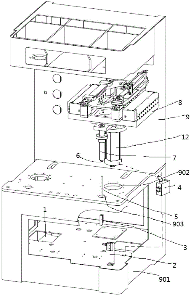
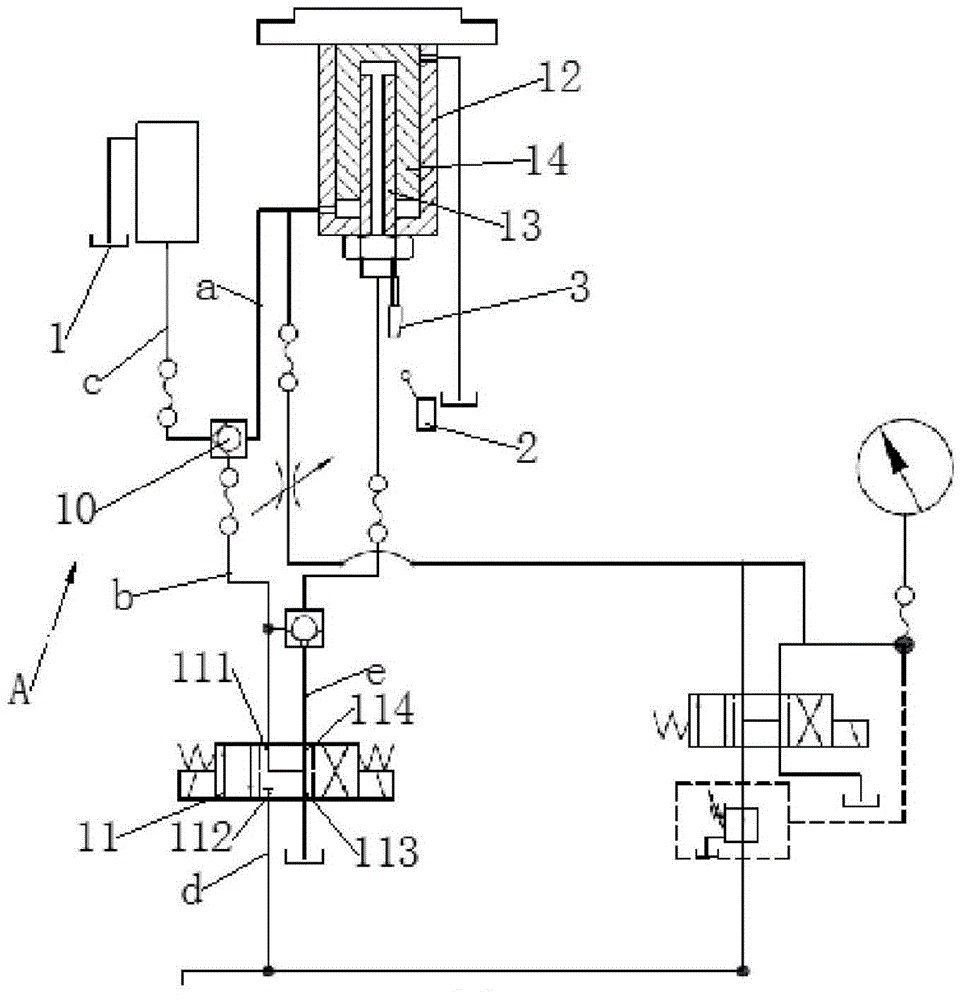
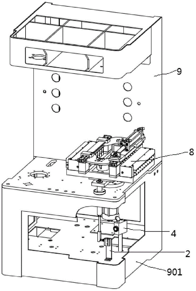
[0027] Such as figure 1 , 2 . As shown in 3, a return buffer mechanism of a bottom pressing machine ...


PUM


Abstract

The invention belongs to the field of shoemaking mechanical equipment, and particularly a return cushioning mechanism of a sole pressing machine, which comprises a sole pressing mechanism, a machine frame and a return cushioning mechanism, wherein the lower end of the sole pressing mechanism is provided with a hydraulic cylinder; the bottom of the machine frame is provided with a base, the middle position is provided with a first through hole, the hydraulic cylinder penetrates through the first through hole, and the sole pressing mechanism is fixed to the machine frame; the return cushioning mechanism is fixed onto the base and connected with the hydraulic cylinder through an oil pipe; the return cushioning mechanism comprises an oil tank fixed in the machine frame, a three-position four-way solenoid valve and a guide check valve; one end of the three-position four-way solenoid valve is connected with the oil tank through an oil pipe; and one end of the guide check valve is connected with the three-position four-way solenoid valve through an oil pipe, one end is connected with the hydraulic cylinder through an oil pipe, and the other end is connected with the oil tank through an oil pipe. The return cushioning mechanism provided by the invention can effectively reduce the impact and vibration in the sole pressing mechanism return process and enhance the processing accuracy of the sole pressing mechanism.

Description

technical field [0001] The invention belongs to the field of shoe-making equipment, and relates to a return buffer mechanism of a sole pressing machine. Background technique [0002] Shoe pressing is an important process to ensure the quality of shoes. The traditional shoemaking process is done by hand. With the improvement of mechanization, professional machinery for shoe pressing has appeared. The bottom pressing machine that is common today, after completing the lifting action and reaching the stroke, the bottom pressing mechanism descends under its own gravity. The descending process of the bottom pressing mechanism is a process in which the acceleration gradually decreases and the speed keeps increasing. At the end of the stroke, the bottom pressing mechanism A large kinetic energy will be obtained, and the impulse force will be released directly on the frame for a short time, resulting in relatively large rigid shock and vibration. [0003] The impulse force and vibra...

Claims


Application Information

Patent Timeline
IPC IPC(8): F15B13/02F15B15/22
Inventor 杨建国杨扬
Owner 大隆机器有限公司
Learn More