Positioning pin positioned taking mechanism

A technology of positioning pins and racks, which is applied in the direction of hand-held tools and manufacturing tools, can solve the problems of wasting beats, increasing manufacturing costs, and increasing labor intensity, and achieve the effects of saving manufacturing costs, reducing beats, and reducing labor intensity

Active Publication Date: 2019-04-19
CHONGQING CHANGAN AUTOMOBILE CO LTD
View PDF6 Cites 3 Cited by
  • Summary
  • Abstract
  • Description
  • Claims
  • Application Information

AI Technical Summary

Problems solved by technology

It is difficult for the operator to take one positioning pin from the material box at a time. In most cases, it is necessary to take several pins at a time, and then take one out of the several pins, and put the rest back into the material box. This method not only increases labor intensity, but also Waste of beats and increase manufacturing costs

Method used


Image

  • Positioning pin positioned taking mechanism
  • Positioning pin positioned taking mechanism
  • Positioning pin positioned taking mechanism

Examples


Embodiment Construction

[0028] The present invention will be further described below in conjunction with accompanying drawing.

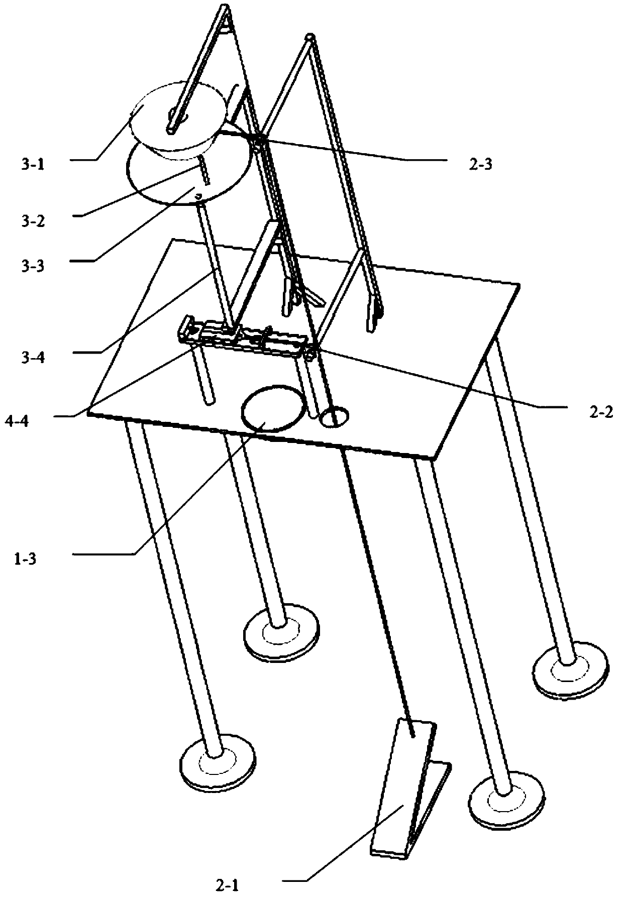
[0029] Such as figure 1 As shown, the positioning pin positioning retrieval mechanism includes a frame, a driver, a distributor and a feeder.

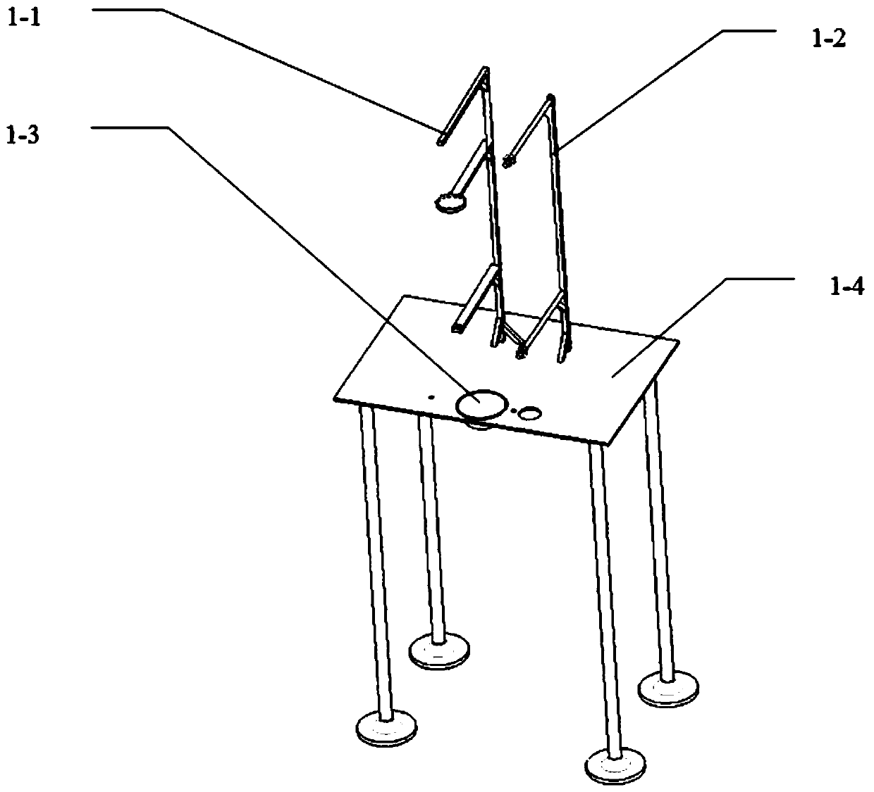
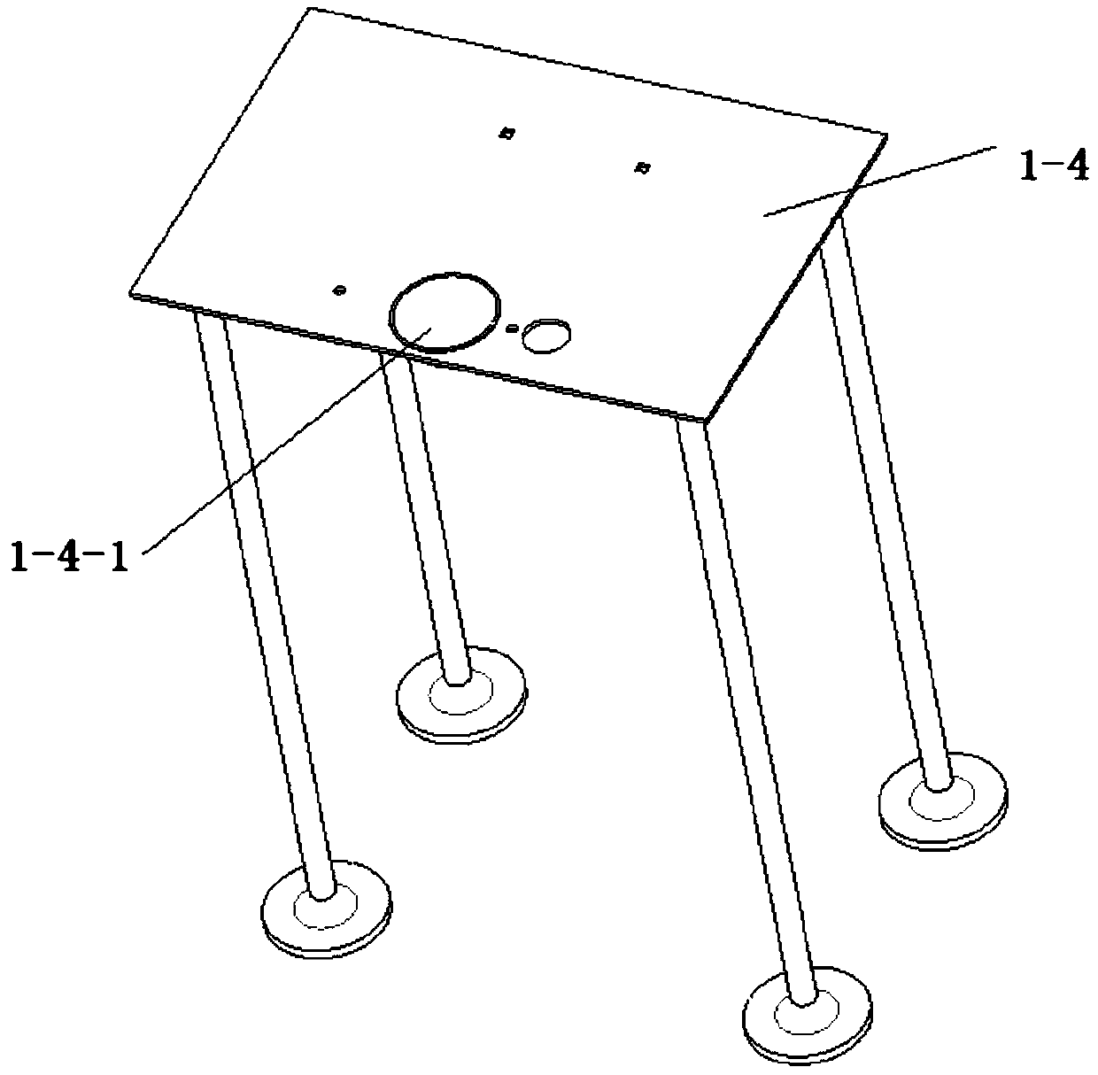
[0030] Such as Figure 2 to Figure 5 The frame includes a left support 1-1, a right support 1-2, a material receiving box 1-3 and a frame body 1-4; the frame body 1-4 is provided with a first through hole 1-4- 1. The material receiving box 1-3 is located in the first through hole 1-4-1. The lower ends of the left support 1-1 and the right support 1-2 are positioned and connected to the frame body 1-4, and the connection between the left support 1-1 and the frame body 1-4 and the right support 1-2 are connected to the frame body 1-4. Reinforcing plates 1-5 are provided at the joints of the frame body 1-4. The left support 1-1 has a first support part 1-1-1, a second support part 1-1-2 and a third support part 1-1-3 in order from ...


PUM


Abstract

The invention discloses a positioning pin positioned taking mechanism. The mechanism comprises a machine frame, a driver, a material distributor and a feeder; the machine frame comprises a left support, a right support, a material receiving box and a machine frame body, wherein the lower ends of the left support and the right support are positioned and connected to the machine frame body; the driver comprises a pedal, a first rope and a second rope, and the lower ends of the first rope and the second rope are connected with the pedal respectively; the feeder comprises a balancer, a stirring rod, a funnel and a pipe body, the balancer is arranged on a first supporting part, a cone pulley inner steel rope of the balancer is connected with the upper end of the first rope, the stirring rod isconnected to a cone pulley of the balancer, the funnel is arranged on a second supporting part, the tube body is arranged on a third supporting part, and the upper end of the tube body is connected with the outlet of the funnel; and the material distributor comprises a sliding groove and a sliding block, the sliding groove is horizontally arranged on the machine frame body, and the sliding block is located in the sliding groove and can move back and forth along the sliding groove between a first position and a second position. According to the mechanism, an operator can be prevented from repeatedly taking and placing positioning pins.

Description

technical field [0001] The invention belongs to the technical field of tooling, and in particular relates to a positioning pin positioning retrieval mechanism. Background technique [0002] At present, the incoming materials of positioning pins on the engine assembly line are stacked in disorder, and the operator mainly takes them from the material box. It is difficult for the operator to take one positioning pin from the material box at a time. In most cases, it is necessary to take several pins at a time, and then take one out of several pins, and put the rest back into the material box. This method not only increases labor intensity, but also A waste of beats increases manufacturing costs. [0003] Therefore, it is necessary to develop a new positioning pin positioning requesting mechanism. Contents of the invention [0004] The purpose of the present invention is to provide a positioning pin positioning retrieval mechanism, which can avoid operators repeatedly taking...

Claims


Application Information

Patent Timeline
Patent Type & Authority Applications(China)
IPC IPC(8): B25B27/00
CPCB25B27/00
Inventor 朱洪磊张玲尧琼林李加彬张劲松黄涛
Owner CHONGQING CHANGAN AUTOMOBILE CO LTD
Why Eureka
Try Eureka