Roller type synchronous locking device

A locking device, roller-type technology, applied in the direction of hand-held tools, manufacturing tools, etc., can solve the problems of restricting the assembly reliability of components, failing to meet assembly requirements, and difficult to control the locking state, so as to achieve simple and labor-saving connecting rod structure, Strong practicability and good reliability

Inactive Publication Date: 2019-04-19
AECC SICHUAN GAS TURBINE RES INST
View PDF9 Cites 4 Cited by
  • Summary
  • Abstract
  • Description
  • Claims
  • Application Information

AI Technical Summary

Problems solved by technology

The locking state is difficult to control and cannot meet the assembly requirements
[0004] The above structure and traditional locking methods seriously restrict the assembly reliability of this component, resulting in the risk of effective locking; at the same time, the greater difficulty of locking directly affects the production tasks of the entire project

Method used


Image

  • Roller type synchronous locking device
  • Roller type synchronous locking device

Examples


Embodiment Construction

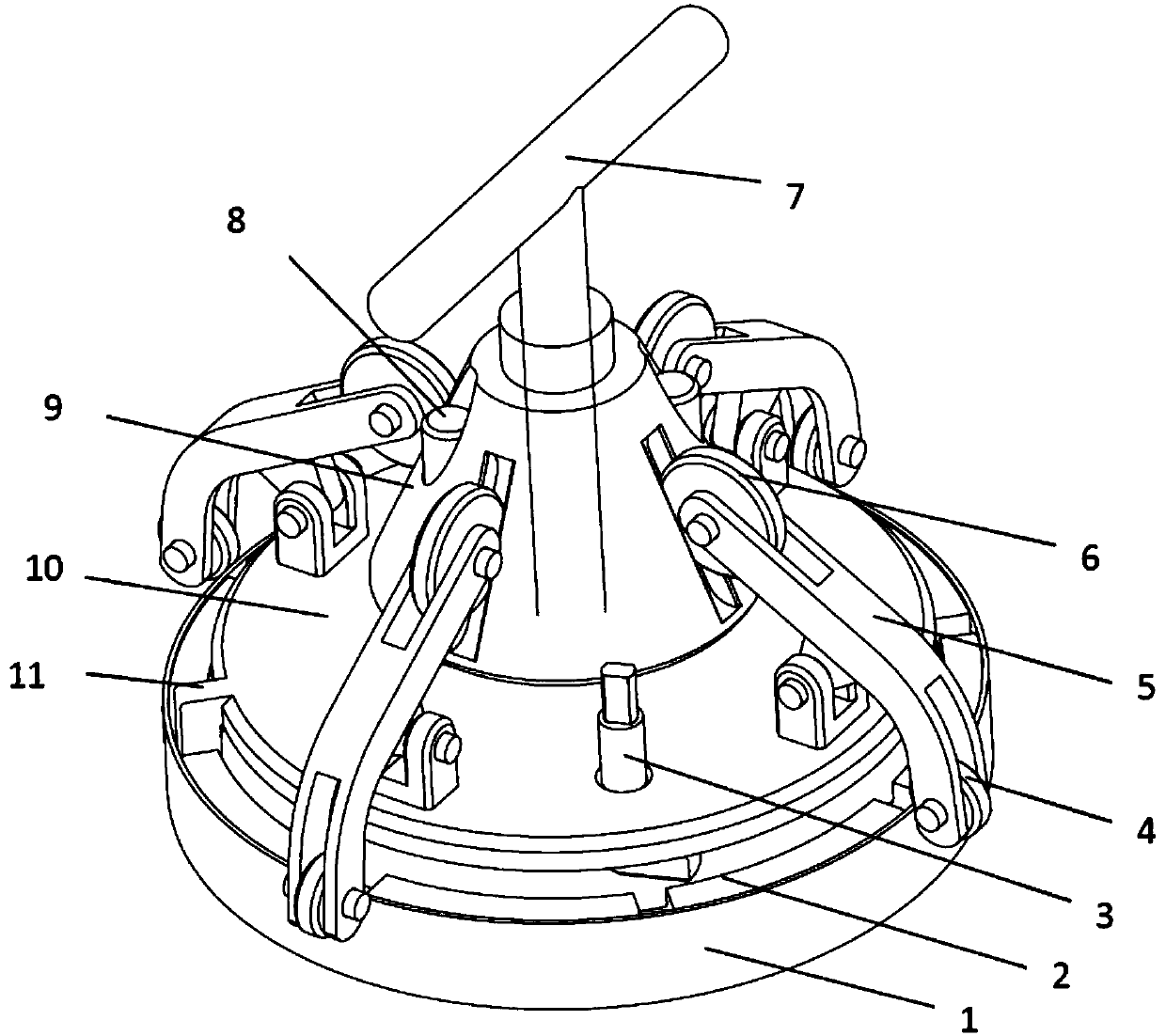
[0016] The present invention will be described in further detail below in conjunction with the accompanying drawings of the description, please refer to figure 2 .

[0017] figure 2 A four-point synchronous roller locking device according to an embodiment of the present invention is shown, and the four-point synchronous roller locking device includes four linkage mechanisms formed by a pressure wheel 4, a connecting rod 5, and a roller 6, a sliding rod 8, and a top plate 10 , The positioning tooth 11 is an integrated top plate structure, the top tool 9 and the ejector rod.

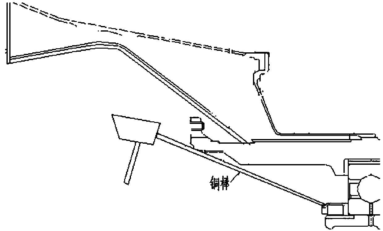
[0018] After the rotation angle of the pressing cam 3, fix the device on the journal to prevent the device from falling off; the positioning teeth 11 in the top plate structure snap into the groove of the shaft end nut 2 to determine the locking position of the lock cup ; The push rod 7 props up on the top plate 10 and spirally moves; the described top tool 9 slides upwards along the slide bar 8, so th...


PUM


Abstract

The invention provides a roller type synchronous locking device aiming to achieve the purposes of efficiently completing a locking task, achieving that a locking cup reliably locks a nut and improvingthe work efficiency and reliability of engine assembly. The roller type synchronous locking device comprises connection rod assemblies and an actuating assembly. Each connection rod assembly comprises a connection rod body, a roller and a compression cam, wherein the roller and the compression cam are rotationally fixed to the two ends of the connection rod body and the compression cam is in contact with the portion to be locked of the locking cup. The actuating assembly comprises a fixed portion ad a moving portion. The fixed portion is fixed to the shaft end, and each connection rod is hinged to the fixed portion. The surface of the movable portion is in contact with each other roller. During synchronous locking, the movable portion moves in the axial direction relative to the fixed portion, so that the rollers are promoted to drive one ends of the connection rod bodies to move, and then the compression cams synchronously lock the to-be-locked portion of a lock cup into a clamping groove structure of a shaft end nut.

Description

technical field [0001] The invention belongs to the technical field of aero-engine assembly, and in particular relates to a roller-type synchronous locking device for a deep-cavity thick-walled lock cup. Background technique [0002] The fastening design of the compression nut at the shaft end of the rotor assembly is widely used in the development of aero-engines. The shaft end nut with a slot structure is locked at multiple points through a lock cup with a suitable thickness to achieve the reliability of the axial parts of the rotor assembly. Tight installation. [0003] However, the structure of the front section of the rotor in a core aircraft project of aviation ( figure 1 ), the design wall thickness of the lock cup is 1.5mm. The conventional locking method is to tap copper rods circumferentially. During this operation, due to the narrow structure space, the force arm at the application point is too long, and the locking is difficult. Usually, only one point is tapp...

Claims


Application Information

Patent Timeline
Patent Type & Authority Applications(China)
IPC IPC(8): B25B27/14
CPCB25B27/143
Inventor 雷琼先杜康兵徐广庆唐文杰白彦徐铭泽
Owner AECC SICHUAN GAS TURBINE RES INST
Why Eureka
Try Eureka