Discharger impeller blade

A technology of impeller blades and fan shut-off, which is applied in the direction of conveyors, transportation and packaging, and conveying bulk materials. Stuck, increase the gap, prevent the effect of impeller blade jamming

Inactive Publication Date: 2019-04-19
ZHENGZHOU JINCHENG CHENGXIN SCREEN EQUIP CO LTD
View PDF9 Cites 0 Cited by
  • Summary
  • Abstract
  • Description
  • Claims
  • Application Information

AI Technical Summary

Problems solved by technology

However, the existing air lock casing and the impeller blades are integrated. During the material feeding and discharging process, along with the rotation of the impeller blades, the feeding of a blade chamber in the impeller blades ends, and the materials begin to collapse and merge with the casing. The contact of the inner wall produces friction, which causes the wear of the casing and impeller blades, thereby reducing the sealing effect of the shut-off fan
At the same time, due to the gap between the casing and the impeller, the material is easily stuck in the gap, causing the fan to be stuck, which is not conducive to the rotation of the fan

Method used


Image

  • Discharger impeller blade
  • Discharger impeller blade
  • Discharger impeller blade

Examples


Embodiment 1

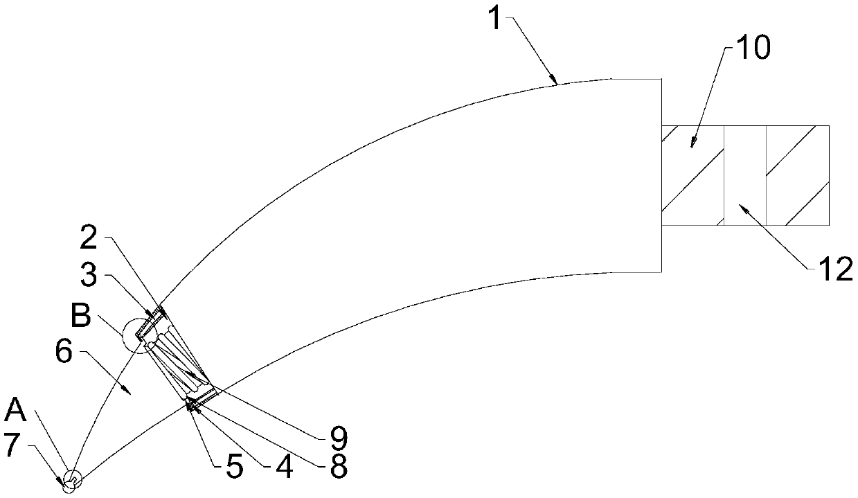
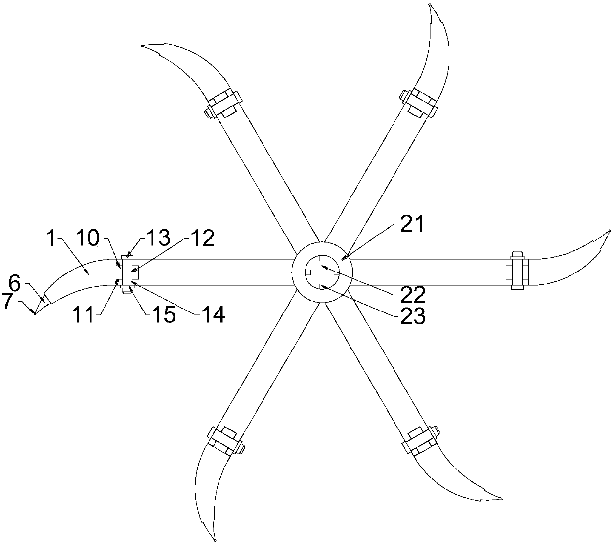
[0029] see Figure 1~4 , an impeller blade for shutting down a fan, comprising an impeller blade 20, a fan block 1 is provided at the front end of the impeller blade 20, a telescopic cavity 2 is provided at the front portion of the fan block 1, a telescopic block 6 is provided at the front end of the telescopic cavity 2, and the telescopic block 6 is near the bottom end The block wall is provided with a first slider 5, the front end of the first slider 5 is provided with a fixed ball 4, the inner wall of the telescopic chamber 2 is provided with a first slideway 3 for locking the fixed ball 4, and the telescopic chamber 2 is provided with a stretching ball. The spring 9, the extension spring 9 is between the telescopic block 6 and the fan block 1.

[0030] In this example, the fan block 1 is fixed on the front end of the impeller blade 20. When the impeller blade 20 rotates inside the blower fan, there is a certain gap between the telescopic block 6 at the front end of the fan...

Embodiment 2

[0032] see Figure 1~4 , an impeller blade for shutting down a fan, comprising an impeller blade 20, a fan block 1 is provided at the front end of the impeller blade 20, a telescopic cavity 2 is provided at the front portion of the fan block 1, a telescopic block 6 is provided at the front end of the telescopic cavity 2, and the telescopic block 6 is near the bottom end The block wall is provided with a first slider 5, the front end of the first slider 5 is provided with a fixed ball 4, the inner wall of the telescopic chamber 2 is provided with a first slideway 3 for locking the fixed ball 4, and the telescopic chamber 2 is provided with a stretching ball. The spring 9, the extension spring 9 is between the telescopic block 6 and the fan block 1.

[0033] The front end of the telescopic block 6 is narrow and the rear end is wide, the surface of the telescopic block 6 is arc-shaped, and the narrow front end reduces the contact surface between the telescopic block 6 and the inn...

Embodiment 3

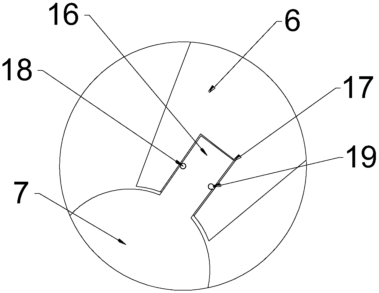
[0036] see Figure 1~4 , an impeller blade for shutting down a fan, comprising an impeller blade 20, a fan block 1 is provided at the front end of the impeller blade 20, a telescopic cavity 2 is provided at the front portion of the fan block 1, a telescopic block 6 is provided at the front end of the telescopic cavity 2, and the telescopic block 6 is near the bottom end The block wall is provided with a first slider 5, the front end of the first slider 5 is provided with a fixed ball 4, the inner wall of the telescopic chamber 2 is provided with a first slideway 3 for locking the fixed ball 4, and the telescopic chamber 2 is provided with a stretching ball. The spring 9, the extension spring 9 is between the telescopic block 6 and the fan block 1.

[0037]The front end of the telescopic block 6 is provided with a soft silica gel ball 7, which can reduce the wear rate between the shut-off fan and the telescopic block 6, thereby effectively discharging materials through the shut...


PUM


Abstract

The invention relates to the technical field of grain processing and discloses a discharger impeller blade. The discharger impeller blade comprises an impeller blade body. The front end of the impeller blade body is provided with a fan block. The front portion of the fan block is provided with an extending-and-contracting cavity. The front end of the extending-and-contracting cavity is provided with an extending-and-contracting block. The block wall, close to the bottom end, of the extending-and-contracting block is provided with a first sliding block. The front end of the first sliding blockis provided with a fixed ball. A first slide way is arranged on the inner wall of the extending-and-contracting cavity, wherein the fixed ball is clamped through the first slide way. An extension spring is arranged in the extending-and-contracting cavity and located between the extending-and-contracting block and the fan block. By means of the discharger impeller blade, the purposes that abrasionbetween a machine casing and the impeller blade body is reduced, and the impeller blade body is prevented from being stuck can be achieved; when the impeller blade body and the machine casing are wornand stuck, the front end of the impeller blade body extends and contracts inwards; the problem that abrasion is increased due to the fact that the impeller blade body and the machine casing are stuckis avoided; a gap formed between the machine casing and the impeller blade body is enlarged; meanwhile, when the front end of the impeller blade body extends and contracts, the sealing performance ofa discharger is not affected; and materials can be discharged more effectively.

Description

technical field [0001] The invention relates to the technical field of grain processing, in particular to a fan impeller blade. Background technique [0002] The air lock is also called the air lock, the unloading valve, the ash unloading valve, and the star unloading machine. The phoenix off device is an important device in the pneumatic conveying and ventilation dust removal network. Its main function is to continuously and timely discharge the materials in the unloader or dust collector, and at the same time ensure that the internal pressure of the equipment is not exposed to the normal pressure environment. It is widely used in pneumatic conveying of equipment in rice milling, milling, feed, machinery and chemical industry, medicine, tobacco, metallurgy, cement and dust removal and unloading of pipe network under pressure. [0003] It plays the role of continuous discharge and air tightness for powdery, granular, flake and fiber materials under positive pressure and neg...

Claims


Application Information

Patent Timeline
Patent Type & Authority Applications(China)
IPC IPC(8): B65G53/46
CPCB65G53/4608
Inventor 高建芳管旭
Owner ZHENGZHOU JINCHENG CHENGXIN SCREEN EQUIP CO LTD
Why Eureka
Try Eureka