Reinforcing device for reinforcing steel member in communication tower

A reinforcement device and steel component technology, which is applied in the direction of towers, building construction, building maintenance, etc., can solve the problems of insufficient bearing capacity of steel components, and achieve the effect of convenient installation and increased bearing capacity

Pending Publication Date: 2019-04-19
ANHUI TELECOMM PLANNING & DESIGNING
View PDF0 Cites 1 Cited by
  • Summary
  • Abstract
  • Description
  • Claims
  • Application Information

AI Technical Summary

Problems solved by technology

However, when using the existing communication tower resources, we often encounter a problem: the load of the re-mounted equipment will exceed the load considered in the original design, resulting in insufficient bearing capacity of some steel components of the original communication tower. Therefore, this steel component needs to be reinforced. How to reinforce the steel member to make it meet the bearing capacity is the problem considered by the present invention

Method used


Image

  • Reinforcing device for reinforcing steel member in communication tower
  • Reinforcing device for reinforcing steel member in communication tower
  • Reinforcing device for reinforcing steel member in communication tower

Examples


Embodiment 1

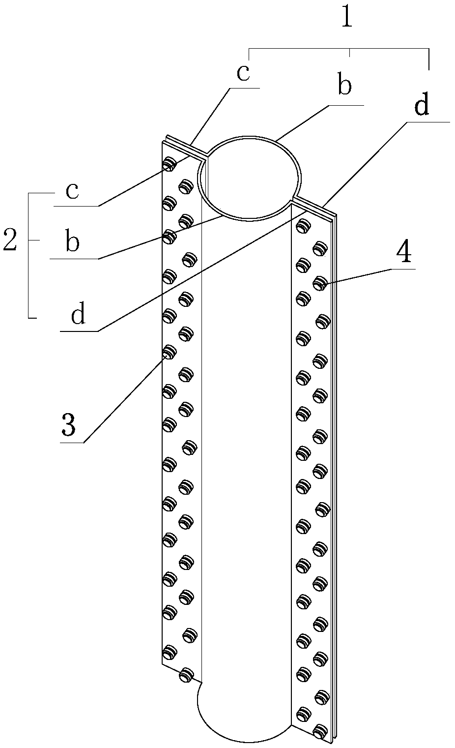
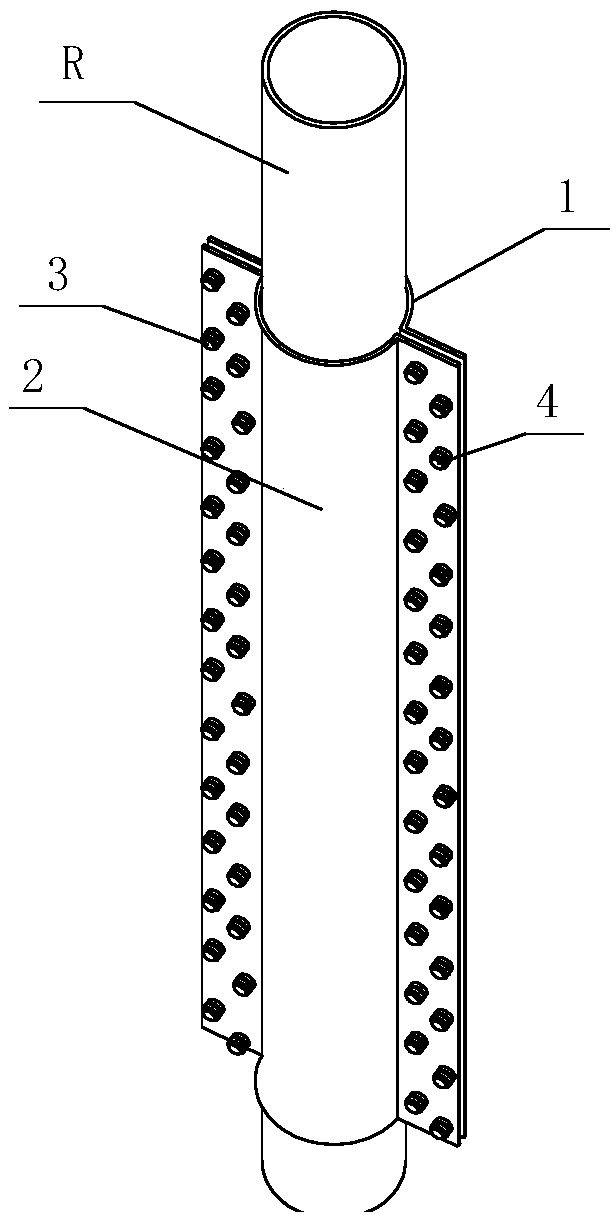
[0030] refer to image 3 , when the steel member R to be reinforced is a columnar structure, the cladding part b is a curved plate, and the first connecting part c and the second connecting part d are planar plates arranged on both sides of the axis of the curved plate , during reinforcement, the first reinforcing body 1 and the second reinforcing body 2 are arranged oppositely on both sides of the columnar steel member R, and the cladding parts b of the two are respectively attached to the outer wall of the steel member R; then Use the first connecting piece 3 to connect the first connecting part c of the first reinforcing body 1 and the first connecting part c of the second reinforcing body 2 together, and use the second connecting piece 4 to connect the second connecting part c of the first reinforcing body 1 part d and the second connecting part d of the second reinforcing body 2 are connected together, and the covering part b of the first reinforcing body 1 and the coveri...

Embodiment 2

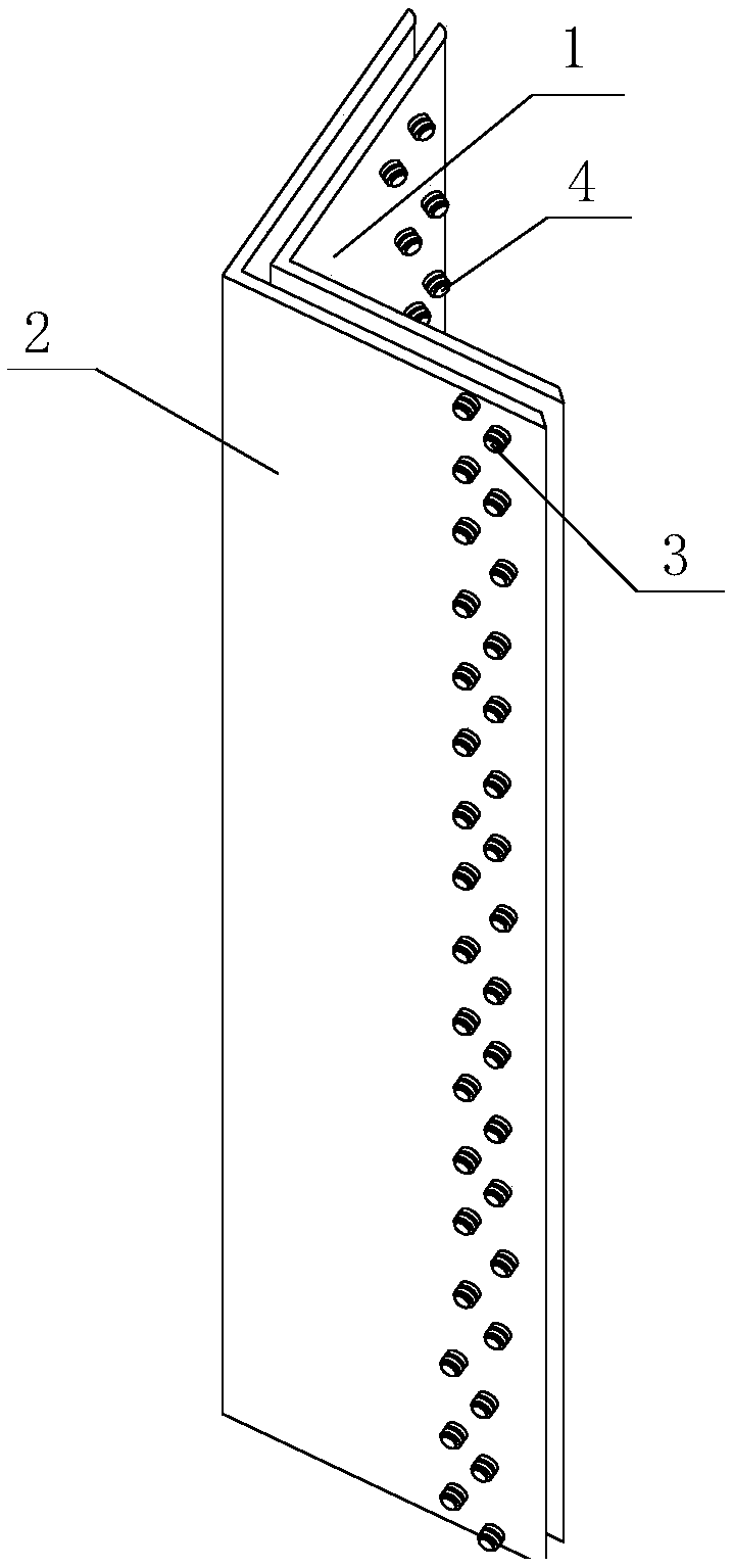
[0032] refer to Figure 4 , when the steel member R to be reinforced is an angle steel structure, the cladding part b is an angle steel, the first connecting part c is located in the same plane as one side of the angle steel, and the second connecting part d is located in the same plane as the other side of the angle steel in plane. When strengthening, the first reinforcing body 1 and the second reinforcing body 2 are arranged on the inside and outside of the angle steel-shaped steel member R, and the cladding parts b of the two are respectively attached to the outer wall of the steel member R; then use The first connection part 3 connects the first connection part c of the first reinforcement body 1 and the first connection part c of the second reinforcement body 2 together, and the second connection part c of the first reinforcement body 1 is connected by the second connection part 4 d and the second connecting part d of the second reinforcing body 2 are connected together,...


PUM


Abstract

The invention discloses a reinforcing device for reinforcing a steel member in a communication tower. The reinforcing device comprises a first reinforcing body and a second reinforcing body. The firstreinforcing body is detachably connected with the second reinforcing body through a connecting mechanism, and while the first reinforcing body is connected with the second reinforcing body, the firstreinforcing body and the second reinforcing body are oppositely arranged and a holding cavity for holding the steel member is formed between two parties. An inner contour shape of the holding cavityis matched with an outer contour shape of the steel member, so that in a reinforcing state of the steel member, the inner wall of the holding cavity contacts with the outer wall of the steel member. Alength of the holding cavity is matched with a length of the steel member, so that in the reinforcing state of the steel member, the length of the holding cavity is greater than 2 / 3 of a total lengthof the steel member. The reinforcing device is capable of solving a problem that carrying capacity of an original steel member of the communication tower is not enough, and conveniently installing, and providing a type of guarantee for using stock communication tower resources better.

Description

technical field [0001] The invention relates to the technical field of telecommunication equipment, in particular to a reinforcing device for reinforcing steel components in a communication tower. Background technique [0002] At present, in order to make better use of existing communication tower resources, it is a development direction for communication tower construction to remount equipment on communication towers that have been put into use. This can save investment, speed up construction progress, and is conducive to environmental protection. However, when using the existing communication tower resources, we often encounter a problem: the load of the re-mounted equipment will exceed the load considered in the original design, resulting in insufficient bearing capacity of some steel components of the original communication tower. Therefore, this steel component needs to be reinforced. How to reinforce the steel member to meet the bearing capacity is the problem consider...

Claims


Application Information

Patent Timeline
IPC IPC(8): E04G23/02E04H12/08
CPCE04G23/0218E04G23/0225E04H12/08
Inventor 张文斌
Owner ANHUI TELECOMM PLANNING & DESIGNING
Why Eureka
Try Eureka