An energy-saving water collector

A water collector and energy-saving technology, applied in the direction of branch pipelines, mechanical equipment, pipes, etc., can solve the problems of increasing pump power waste, consuming water flow energy, increasing operating costs, etc., to reduce turbulent impact and reduce noise , smooth water effect

Inactive Publication Date: 2019-08-16
SHANDONG LABOR VOCATIONAL & TECHN COLLEGE
View PDF6 Cites 0 Cited by
  • Summary
  • Abstract
  • Description
  • Claims
  • Application Information

AI Technical Summary

Problems solved by technology

However, with such a setting method, after the outlet water flow of the pump enters the water collector through the water inlet, it will have a strong impact on the inner wall of the water collector. Huge noise is generated, and the energy of the water flow is consumed; since the energy of the water flow is mainly obtained by the pressure provided by the pump in the pump room system, the consumed energy needs to be filled by the pump to provide additional energy, which increases the The waste of pump power also increases the operating cost

Method used


Image

  • An energy-saving water collector
  • An energy-saving water collector
  • An energy-saving water collector

Examples


Embodiment 1

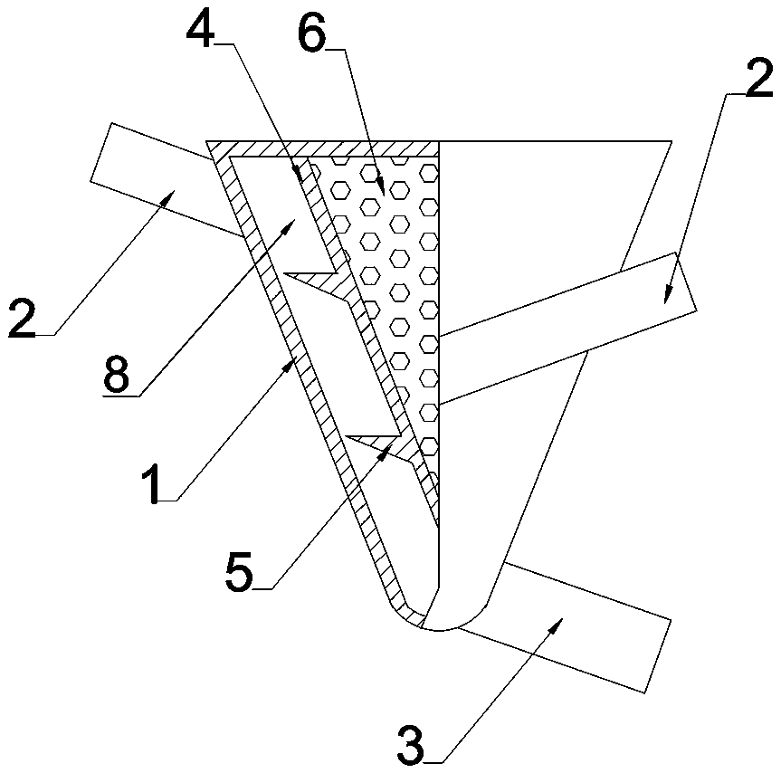
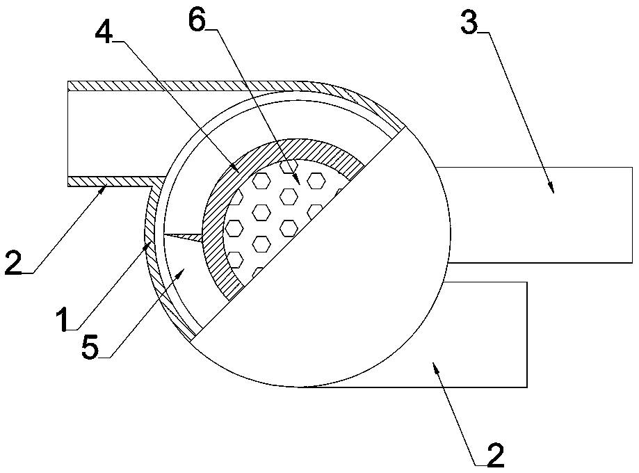
[0028] Such as Figure 1 to Figure 4 As shown, this embodiment is an energy-saving water collector, which includes a housing 1, a water outlet pipe 3 and at least one water inlet pipe 2.

[0029] The casing is conical, and a conical guide core 4 is sleeved in the casing 1; the surface of the casing 1 and the guide core 4 are parallel with a gap 8 therebetween; the guide core 4 ends are connected to the housing 1 by welding or bolts.

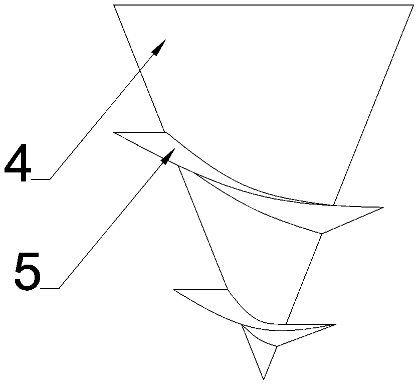
[0030] The outer surface of the guide core 4 is provided with a guide device 5; the guide device 5 is a continuous spiral protrusion. The cross section of the spiral protrusion is a right-angled triangle or an obtuse-angled triangle, and one side of the right-angled side or the obtuse-angled side faces the water inlet direction. This setting method restricts the lateral direction of the water flow (also in the axial direction of the water trap), so that the influent water flow is kept as independent as possible, and it does not interfere with the wa...

Embodiment 2

[0043] This embodiment is also an energy-saving water collector. Compared with embodiment 1, the basic structure is similar, the difference is mainly: the number of water inlet pipes 2 is 3, and the height of the deflector 5 is equal to 1 / 2 of the height of the gap 8. , The distance between the two adjacent spirals of the guide device 5 is the same as the gap; the angle between the water inlet pipe and the water collector axis is 90°; the diameter of the water inlet pipe is 1 / 2 of the height of the gap 8; The diameter of the water pipe is equal to the height of the gap 8; the cone apex angle of the casing and the guide core 4 is 60°.

[0044] During the verification process, it was found that if the height of the spiral protrusion of the diversion device 5 is lower than 1 / 2 of the height of the gap 8, it is difficult to ensure the lateral restriction of the water flow direction. Therefore, it is better to be no less than 1 / 2. This implementation In the example, the height of the ...

Embodiment 3

[0050] This embodiment is also an energy-saving water collector. Compared with embodiment 1, the basic structure is similar, and the main difference is: the number of water inlet pipes 2 is 4; the height of the deflector 5 is the height of the gap 8 3 / 5; the distance between the two adjacent spirals of the guide device 5 is 1.5 times the height of the gap 8; the angle between the water inlet pipe and the axial direction of the water flow in the water collector is 110°; the housing The cone apex angle of the guide core (4) is 90°.

[0051] The diameter of the inlet pipe is 7 / 12 of the height of the gap (8); the diameter of the outlet pipe is 1.5 times the height of the gap (8). According to the circle area formula πr 2 , We can calculate that, in this embodiment, the diameter of the outlet pipe 3 is greater than or equal to the diameter of the inlet pipe 2, that is, 7 / 12 of the height of the gap 8. The arrangement of this embodiment will not cause insufficient drainage.


PUM


Abstract

The invention relates to an energy-saving type water collecting device. The water collecting device comprises a shell, a water outlet pipe and at least one water inlet pipe; the shell is conical, a conical flow guide core is sleeved with the shell, a spiral flow guide device is arranged on the outer surface of the flow guide core, the water inlet pipes are evenly distributed on the outer side of the shell and are tangent with the shell, and the tangent position is located between two adjacent spirals of the flow guide device; the water flow of the water inlet pipes are the same with the spirals of the flow guide device in the rotating direction of the shell, the water outlet pipe is located at the end of the shell and is tangent with the shell, and the water outlet direction of the water outlet pipe is the same with the spiral direction of the flow guide device. Through the cooperative arrangement of the flow guide core, the shell and the flow guide device, water flows in the water collecting device run in a sequential manner, the turbulent impact is reduced as much as possible, the water flow internal consumption is reduced, two problems of impact losses and noise in the prior artcan be solved, and the positive technical significance is achieved.

Description

Technical field [0001] The invention relates to an energy-saving water collector, which belongs to the technical field of water resources transportation and management. Background technique [0002] In the current field of water resources transportation and management, a multi-pump pump room system is often used; in order to ensure the stability of pipeline water supply, the outlet pipes of multiple pumps are generally connected to a water collector for mixed flow. In the prior art, the connection between the pump outlet pipe (equivalent to the water inlet pipe of the water collector) and the water collector usually adopts the way that the center line intersects vertically, so that the connection part is more symmetrical, which is convenient for positioning and stress balance. However, with this arrangement, the outlet water flow of the pump enters the water collector through the water inlet and will have a strong impact on the inner wall of the water collector. After reflection...

Claims


Application Information

Patent Timeline
Patent Type & Authority Patents(China)
IPC IPC(8): F16L41/02
CPCF16L41/02
Inventor 韩刚李辉杨建波
Owner SHANDONG LABOR VOCATIONAL & TECHN COLLEGE
Why Eureka
Try Eureka