
Armored strain monitoring optical cable and soil covering monitoring and stress calibration method

A strain monitoring and armoring technology, applied in optics, light guides, measuring devices, etc., can solve the problems of low survival rate, easy slippage of optical cables, poor mechanical properties, etc., and achieve high measurement accuracy, good performance-price ratio, and simple installation. Effect

Pending Publication Date: 2019-04-19
南京嘉兆仪器设备有限公司
View PDF0 Cites 2 Cited by
  • Summary
  • Abstract
  • Description
  • Claims
  • Application Information

AI Technical Summary

Problems solved by technology

However, the existing strain monitoring optical cable has poor mechanical properties, low survival rate after direct burial laying, and easy slippage between the various structural parts of the optical cable.

Method used


Image

  • Armored strain monitoring optical cable and soil covering monitoring and stress calibration method
  • Armored strain monitoring optical cable and soil covering monitoring and stress calibration method
  • Armored strain monitoring optical cable and soil covering monitoring and stress calibration method

Examples


Embodiment Construction

[0024] Below in conjunction with accompanying drawing and specific embodiment, further illustrate the present invention, should be understood that these examples are only for illustrating the present invention and are not intended to limit the scope of the present invention, after having read the present invention, those skilled in the art will understand various aspects of the present invention All modifications of the valence form fall within the scope defined by the appended claims of the present application.

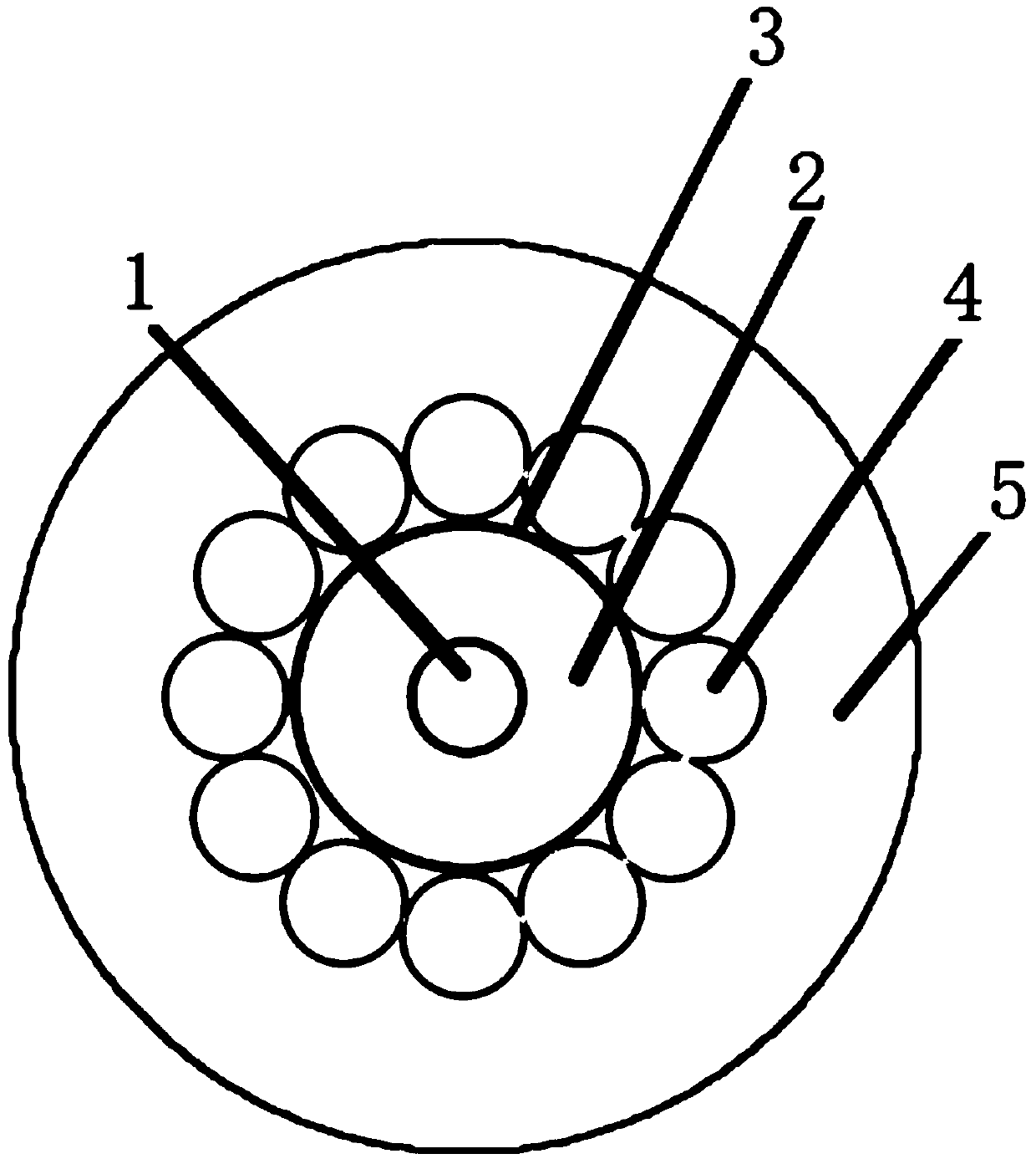
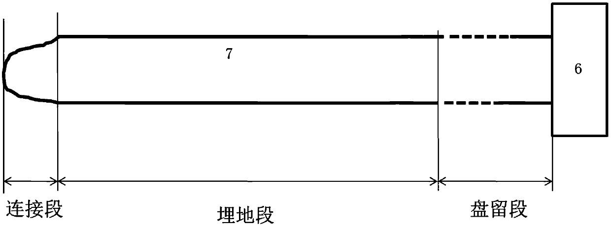
[0025] An armored strain monitoring optical cable, such as figure 1 , 2 As shown, it includes a fiber core (1), a steel loose tube (3), a steel wire armor (4), and an outer sheath (5) arranged in sequence from inside to outside, and the fiber core (1) is a single-mode optical fiber , the filling ointment (2) is filled between the fiber core (1) and the loose steel tube (3), the filling ointment (2) adopts LHAX ointment; the outer sheath (5) adopts high Density poly...


PUM


Abstract

The invention discloses an armored strain monitoring optical cable and a soil covering monitoring and stress calibration method. The armored strain monitoring optical cable comprises a fiber core (1),a steel loose tube (3), a steel wire armor (4) and an outer sheath (5), and cable jelly (2) is filled between the fiber core (1) and the steel loose tube (3). The armored strain monitoring optical cable has advantages that excellent mechanical properties, tensile resistance, pressure resistance and remarkable rat damage prevention performances are realized, and the survival rate is greatly increased after direct burial laying; structural portions of the optical cable are closely attached without slipping, so that the stress transfer performance is effectively guaranteed, and high sensitivityand accuracy of strain data are achieved.

Description

technical field [0001] The invention relates to an armored strain monitoring optical cable and a soil covering monitoring and stress calibration method, belonging to the fields of structural health and geological disaster monitoring. Background technique [0002] With the progress of society and the development of economy, a large number of engineering constructions are carried out in various places, and more buildings with strange shapes and large scales appear all over the world. Due to defects in design and construction quality, engineering buildings are deformed during construction and operation. If the deformation exceeds the limit, it will affect the use of the building and even cause accidents such as collapse. Because deformation monitoring can provide necessary information for judging the safety of engineering buildings, the significance of deformation monitoring is more important. Geological disaster monitoring refers to the use of various technologies and methods...

Claims


Application Information

Patent Timeline
Patent Type & Authority Applications(China)
IPC IPC(8): G02B6/44G01B11/16
CPCG01B11/18G02B6/443
Inventor 接智成吴帅胡德新邵翰林史波
Owner 南京嘉兆仪器设备有限公司
Learn More