Container laser scanning recognition method, device, electronic equipment and readable medium

A laser scanning and container technology, applied in the field of laser scanning, can solve the problems of low accuracy, the container cannot obtain the attitude of the spreader, and the attitude of the spreader cannot be obtained, and achieves the effect of increasing the accuracy

Active Publication Date: 2021-12-17
SANY MARINE HEAVY IND
View PDF0 Cites 0 Cited by
  • Summary
  • Abstract
  • Description
  • Claims
  • Application Information

AI Technical Summary

Problems solved by technology

Fully automatic picking and placing containers through image recognition is easily affected by changes in the external environment. For example, in rainy, snowy and other weather, the accuracy of image recognition will decrease, thereby affecting the accuracy of fully automatic picking and placing containers; moreover, image recognition cannot be acquired The attitude of the spreader, thus affecting the accuracy of fully automatic picking and placing containers
[0004] Aiming at the problem in the above-mentioned prior art that the fully automatic picking and placing of containers through image recognition cannot obtain the attitude of the spreader and the accuracy is low, no effective solution has been proposed so far

Method used


Image

  • Container laser scanning recognition method, device, electronic equipment and readable medium
  • Container laser scanning recognition method, device, electronic equipment and readable medium
  • Container laser scanning recognition method, device, electronic equipment and readable medium

Examples


Embodiment 1

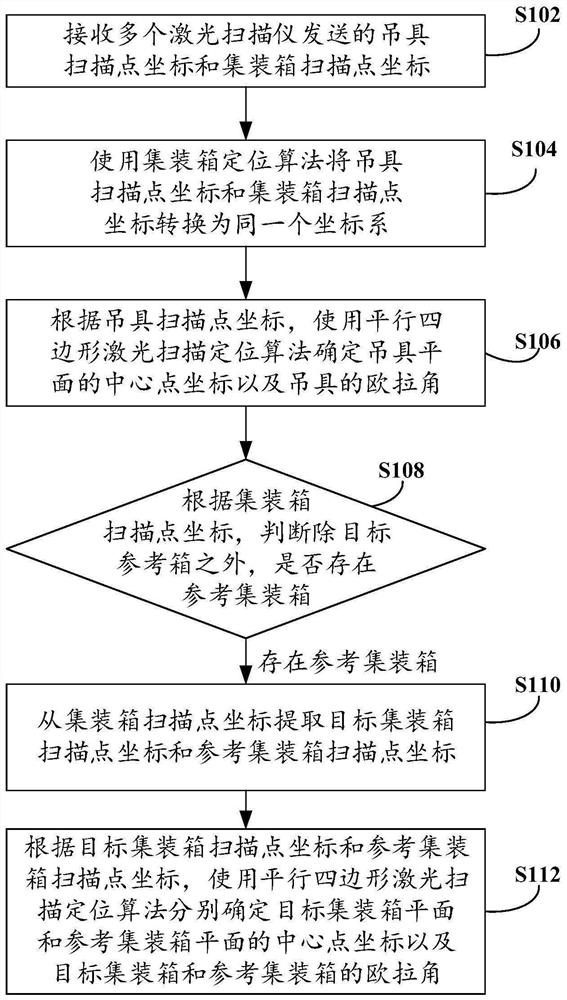
[0034] Embodiment 1 of the present invention provides a container laser scanning identification method, see figure 1 The flow chart of a container laser scanning identification method shown includes the following steps:

[0035] Step S102, receiving the coordinates of the scanning point of the spreader and the coordinates of the scanning point of the container sent by multiple laser scanners.

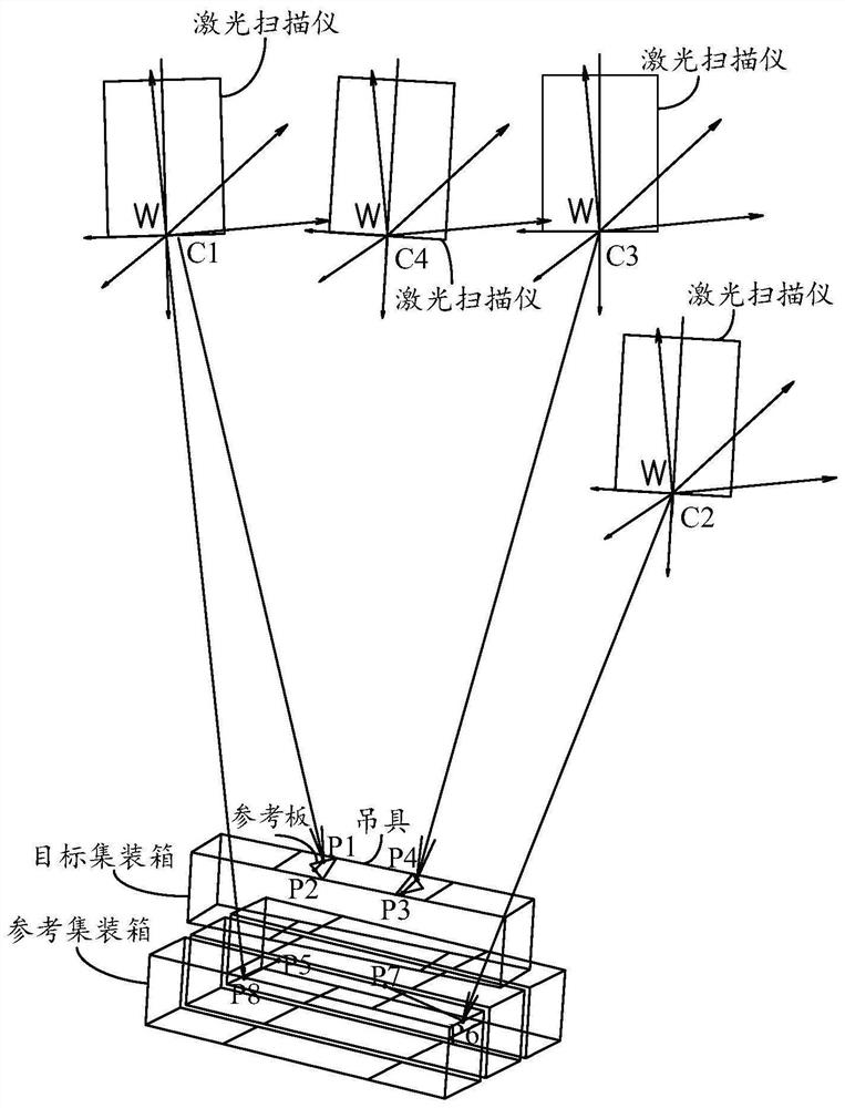
[0036] There are at least two laser scanners, typically four, which are respectively installed on the four corners under the trolley. Among all the scanners, the scanning directions of two scanners are parallel, and the scanning directions of the remaining scanners are It is necessary to ensure that the scanning directions of all scanners cannot be all parallel. At least three scanning directions of the scanners must intersect each other. It is necessary to ensure that the points scanned by all scanners can form different planes instead of only in one plane. Therefore, the number of co...

Embodiment 2

[0127] Embodiment 2 of the present invention provides a container laser scanning identification device, see Figure 7 The schematic structural diagram of a container laser scanning identification device shown includes a coordinate receiving module 71, a coordinate system conversion module 72, a spreader calculation module 73, a container judgment module 74, a coordinate extraction module 75 and a container calculation module 76. The function is as follows:

[0128] A coordinate receiving module 71, configured to receive the coordinates of the spreader scanning point and the coordinates of the container scanning point sent by multiple laser scanners;

[0129] The coordinate system conversion module 72 is used to convert the coordinates of the spreader scanning point and the coordinates of the container scanning point into the same coordinate system by using the container positioning algorithm;

[0130] The spreader calculation module 73 is used to determine the coordinates of ...


PUM


Abstract

The invention provides a container laser scanning identification method, device, electronic equipment and readable medium, relating to the technical field of laser scanning, including: receiving the coordinates of the scanning point of the spreader and the coordinates of the scanning point of the container sent by multiple laser scanners; The container positioning algorithm converts the coordinates of the scanning point of the spreader and the coordinates of the scanning point of the container into the same coordinate system; uses the parallelogram laser scanning positioning algorithm to determine the coordinates of the center point of the spreader plane and the Euler angle of the spreader; In addition, whether there is a reference container; if there is a reference container, extract the target container scanning point coordinates and reference container scanning point coordinates from the container scanning point coordinates; use the parallelogram laser scanning positioning algorithm to determine the spreader plane, target container plane and reference container respectively The coordinates of the center point of the plane and the Euler angles of the spreader and container. The attitude of the spreader and the container can be obtained to realize the automatic picking and placing of the container in the yard.

Description

technical field [0001] The invention relates to the technical field of laser scanning, in particular to a container laser scanning identification method, device, electronic equipment and readable medium. Background technique [0002] With the development of economy and technology, more high-tech applications are applied to terminals, and terminal automation has become the main goal of current terminal development. In the process of terminal automation, there has been a trend of transition from semi-automatic picking and placing containers to fully automatic picking and placing containers. Laser scanning is a widely used scanning method at present. The application of laser scanning in terminal automation is mainly to install laser scanners on trolleys to achieve anti-collision lifting, rather than fully automatic picking and placing containers. [0003] At present, the main solution to realize automatic picking and placing of containers is to install a camera on the spreader...

Claims


Application Information

Patent Timeline
Patent Type & Authority Patents(China)
IPC IPC(8): G06K7/14
CPCG06K7/1439G06K7/146
Inventor 王君雄梁柱健唐修俊
Owner SANY MARINE HEAVY IND
Why Eureka
Try Eureka