Circuit breaker arc-extinguishing device

A technology of arc striking device and circuit breaker, which is applied in the direction of circuit breaker components, circuits, electrical components, etc. It can solve the problems of weak electric field, long arc burning time, and fast contact ablation, so as to strengthen the strength of the magnetic field, The effect of shortening the arcing time and obvious economic benefits

Inactive Publication Date: 2019-04-19
江苏高博锐电气有限公司
View PDF0 Cites 0 Cited by
  • Summary
  • Abstract
  • Description
  • Claims
  • Application Information

AI Technical Summary

Problems solved by technology

However, iron material is a magnetic material. Although the magnetic field around the arc is enhanced, the iron material itself has a large resistance and a weak electric field effect. The burning time on the contacts is long, resulting in fast ablation of the contacts, which is not conducive to breaking the product and reducing the electrical life of the product
In addition, there are also relevant literatures that put the coil into the contact system to enhance the magnetic field, but this approach is not worth promoting. The reason is that the coil must be energized first to generate a magnetic field, and a short circuit is likely to occur between the arc and the charged coil. cause safety hazard
Secondly, the high temperature of the arc has a very large impact on the coil itself
In addition, the coil needs a power supply, and its circuit structure design has many factors to consider, which is relatively complicated, which is not conducive to the improvement of production and economic benefits.

Method used


Image

  • Circuit breaker arc-extinguishing device
  • Circuit breaker arc-extinguishing device

Examples


Embodiment Construction

[0016] The present invention is described in detail below in conjunction with accompanying drawing and specific embodiment:

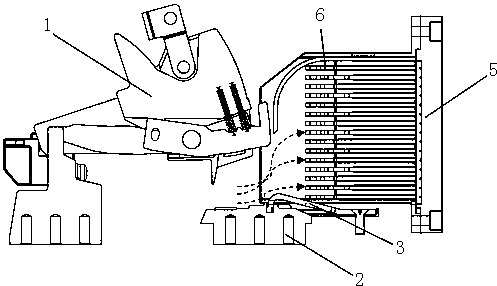
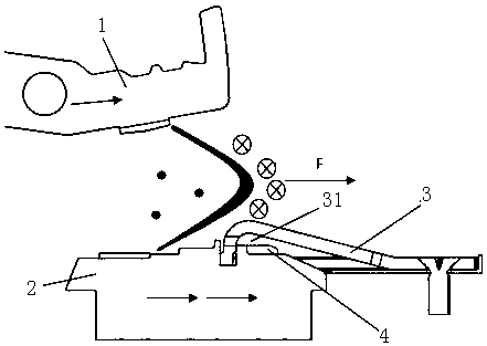
[0017] Such as figure 1 with figure 2 The shown arc striking device of a circuit breaker includes a moving contact 1, a static contact 2, an arc striking piece 3, a magnetizing block 4 and an arc extinguishing chamber 5, and an arc extinguishing grid is arranged at the front end of the arc extinguishing chamber 5 6. The moving contact 1 is located above the static contact 2, the front end of the arc striker 3 is fixedly installed on the static contact 2, the middle and tail of the arc striker 3 are suspended in the air, and the arc striker 3 is suspended in the air. The tail of the arc plate 3 extends to the lower part of the arc extinguishing grid 6, and the charged particles in the arc quickly enter the arc extinguishing chamber 5 along the arc plate. There is a gap 31 between the front end of the arc plate 3 and the static contact 2 , the magnetiz...


PUM


Abstract

The invention discloses a circuit breaker arc-extinguishing device. The circuit breaker arc-extinguishing device comprises a movable contact, a static contact, an arc-inducing piece, a magnetizing block and an arc extinguishing chamber. The front end of the arc extinguishing chamber is provided with an arc-extinguishing grating, the movable contact is located at the upper portion of the static contact, the head of the front end of the arc-inducing piece is fixedly installed on the static contact, the middle portion and the tail portion of the arc-inducing piece are suspended, the tail portionof the arc-inducing piece is extended to the lower portion of the arc-extinguishing grating, there is a gap between the front end of the arc-extinguishing grating and the static contact, the magnetizing block is arranged in the gap, and the magnetizing block is fixedly installed on the static contact. Charged particles in the arc quickly enter the direction of the arc extinguishing chamber along the arc-inducing piece of the copper materials, the magnetizing block can improve the power of the density of the magnetic field to enhance the magnetic field so as to increase the electric power in the tangential direction, and therefore, the simultaneous effects of the electric field and the magnetic field can improve the movement speed of the arc in the tangential direction to enter the arc extinguishing chamber in a shorter time.

Description

technical field [0001] The invention belongs to the technical field of low-voltage power distribution equipment, and in particular relates to an arc striking and guiding structure and device for a circuit breaker. Background technique [0002] Arc extinguishing is an important application of low-voltage switches. The design requirements of switchgear are not only to achieve zero arcing, but also the test and detection of arcs is also very strict, because arcs not only cause damage to equipment and lines, but also affect personal safety. Especially for universal circuit breakers, since the operating current is usually large, a large number of arcs are generated at the moment of breaking the contacts. How to quickly eliminate the arc in a short time is a big test for the circuit breaker. [0003] The arc movement mainly follows the normal velocity in the direction of head breaking, while the tangential direction makes the arc elongate due to the existence of the magnetic fiel...

Claims


Application Information

Patent Timeline
Patent Type & Authority Applications(China)
IPC IPC(8): H01H73/18H01H9/44
CPCH01H73/18H01H9/44
Inventor 刘言菊朱金星李大意段新高邓高见
Owner 江苏高博锐电气有限公司
Why Eureka
Try Eureka