
Internal carbon rod positioning and installation equipment for battery automatic production

A technology for positioning and installing carbon rods, which is applied in the field of internal carbon rod positioning and installation equipment for automatic battery production, can solve problems such as carbon rod damage, low production efficiency, and carbon rod matching and installation errors.

Inactive Publication Date: 2019-04-19
胡旭燕
View PDF0 Cites 5 Cited by
  • Summary
  • Abstract
  • Description
  • Claims
  • Application Information

AI Technical Summary

Problems solved by technology

[0004] The purpose of the present invention is to provide an internal carbon rod positioning and installation device for automatic battery production to solve the existing carbon rod installation work proposed in the above background technology. In order to ensure that the carbon rod is installed well and the position of the carbon rod is correct, Manuals are often used instead of machines, resulting in low production efficiency and labor-intensive. At the same time, the operator has been in contact with the battery and the inner core of the battery for a long time, and the chemical electrolyte in the battery will cause certain harm to the human body. For the automatic installation of carbon rod equipment, its The accuracy is poor, and there is a certain error in the installation of the carbon rod. At the same time, after the carbon rod is loaded into the battery, it is easy to damage or break the carbon rod due to the uneven force on the carbon rod.

Method used


Image

  • Internal carbon rod positioning and installation equipment for battery automatic production
  • Internal carbon rod positioning and installation equipment for battery automatic production
  • Internal carbon rod positioning and installation equipment for battery automatic production

Examples


Embodiment Construction

[0029] The following will clearly and completely describe the technical solutions in the embodiments of the present invention with reference to the accompanying drawings in the embodiments of the present invention. Obviously, the described embodiments are only some, not all, embodiments of the present invention. Based on the embodiments of the present invention, all other embodiments obtained by persons of ordinary skill in the art without making creative efforts belong to the protection scope of the present invention.

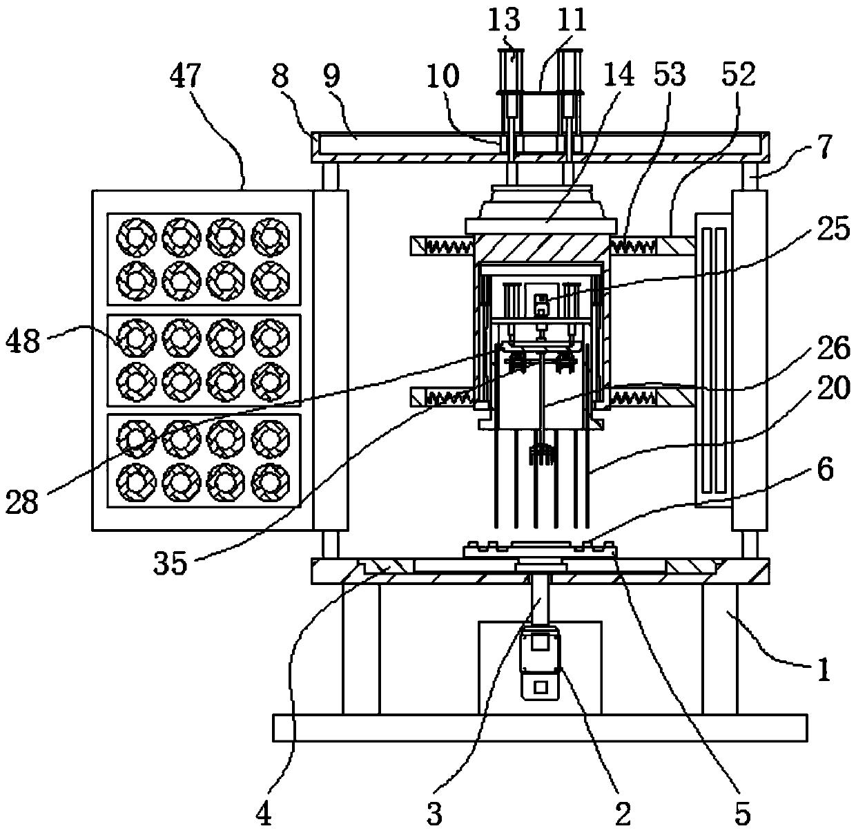
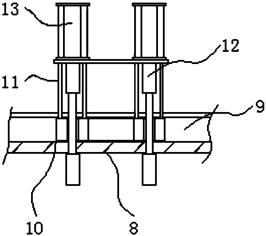
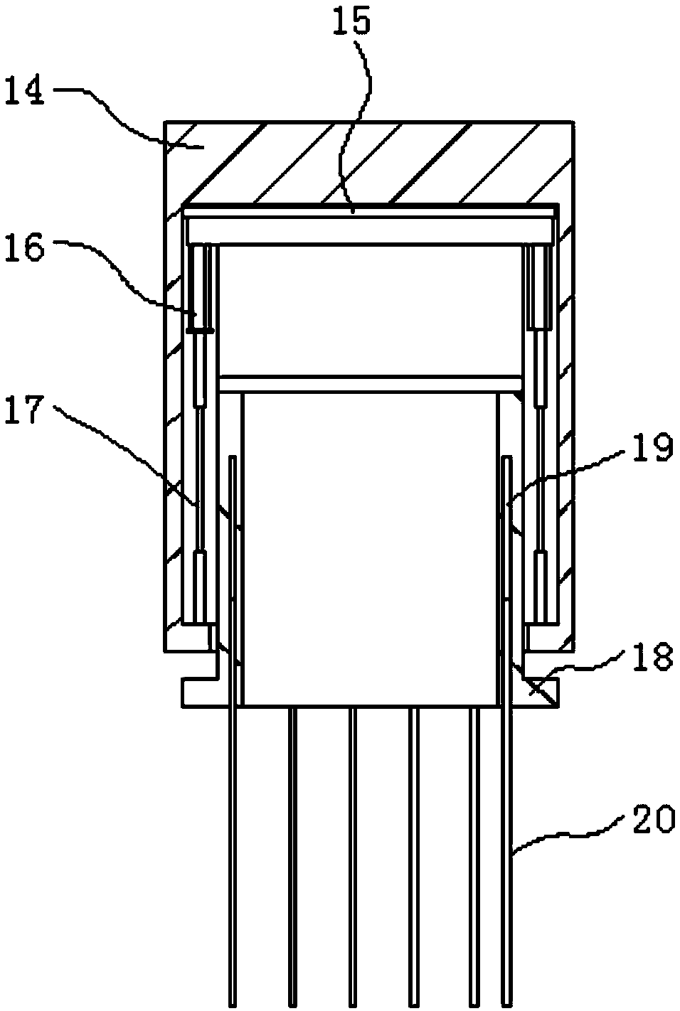
[0030] see Figure 1-8 , the present invention provides a technical solution: an internal carbon rod positioning and installation device for automatic battery production, including a base frame 1 and an installation cylinder 14, a bottom motor 2 is installed in the middle of the base frame 1, and the shaft end of the bottom motor 2 A transmission shaft 3 is provided, a rotating tray 4 is placed inside the upper surface of the base frame 1, and a placement plat...


PUM


Abstract

The invention discloses internal carbon rod positioning and installation equipment for battery automatic production. The internal carbon rod positioning and installation equipment comprises a base frame and a mounting cylinder, wherein a bottom motor is installed in the middle of the base frame, a shaft end of the bottom motor is provided with a transmission shaft, a rotating tray is arranged inside the upper surface of the base frame, a placing board is fixed on the upper surface of the rotating tray, supporting stand frames are arranged on the left and right sides of the upper surface of thebase frame, a rubber pad is arranged inside the mounting cylinder, and the mounting cylinder is arranged below first hydraulic telescopic rods. Through the arrangement of the bottom motor, the transmission shaft and the rotating tray, the internal carbon rod positioning and installation equipment for battery automatic production enables the base frame to be equipped with the rotating movable structure, a clamping ring on the placing board is used for clamping and fixing a battery shell body, the rotating tray can rotate under the action of the bottom motor and the transmission shaft so as toperform reversing adjustment on the placing board, and the placing board can move horizontally on the rotating tray so as to adjust the placing position of the battery shell body.

Description

technical field [0001] The invention relates to the technical field of battery production equipment, in particular to an internal carbon rod positioning and installation equipment for automatic battery production. Background technique [0002] A dry battery is a chemical battery that uses a paste electrolyte to generate direct current (a wet battery is a chemical battery that uses a liquid electrolyte). It is roughly divided into primary batteries and secondary batteries, which are commonly used in daily life, and Lightweight batteries, common dry batteries are mostly manganese-zinc batteries, the middle is a positive electrode carbon rod, outsourced with a mixture of graphite and manganese dioxide, and then a layer of fiber mesh, coated with a thick electrolyte paste, the outermost layer is metal zinc The barrel made of leather, that is, the negative electrode, and the carbon rod play an important role in the structure of the dry battery, so the installation of the carbon r...

Claims


Application Information

Patent Timeline
IPC IPC(8): H01M6/00H01M6/06
CPCH01M6/005H01M6/06
Inventor 胡旭燕
Owner 胡旭燕
Learn More