Supercharge Your Innovation With Domain-Expert AI Agents!

Electromagnetic resonance intelligent wireless charge system and method for use with charge

A wireless charging and resonant technology, applied in battery circuit devices, current collectors, electric vehicles, etc., can solve the problem of not being able to effectively manage the various states of the energy storage element on the mouse side and leaving the charging area status indication, the inconvenience of equipment use, and the impact of use, etc.

Pending Publication Date: 2019-04-19
DONGGUAN TOGRAN ELECTRONICS TECH
View PDF5 Cites 1 Cited by
  • Summary
  • Abstract
  • Description
  • Claims
  • Application Information

AI Technical Summary

Problems solved by technology

[0002] With the development and progress of technology, more and more wireless mice and other wireless devices need to be charged. Whenever they are in use, they need to pay attention to the power status. Every time they charge, they need to find a charging cable and plug in the charging cable to charge the device, and Affects the use of the device during charging or causes inconvenient use
[0003] In order to further improve the user experience and solve the problem that some current mouse kits with charging while moving cannot effectively manage the various states of the energy storage components on the mouse side during the charging process and the status indication of the out-of-charging area, it is necessary to study a set of New Wireless Charging System

Method used


Image

  • Electromagnetic resonance intelligent wireless charge system and method for use with charge
  • Electromagnetic resonance intelligent wireless charge system and method for use with charge
  • Electromagnetic resonance intelligent wireless charge system and method for use with charge

Examples


Embodiment Construction

[0044] The present invention is further described in conjunction with the following examples.

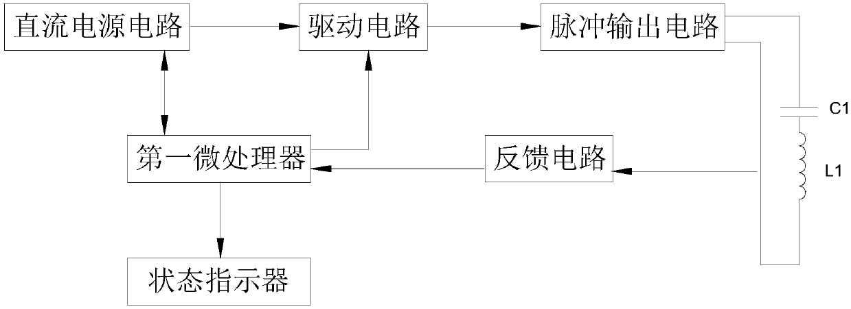
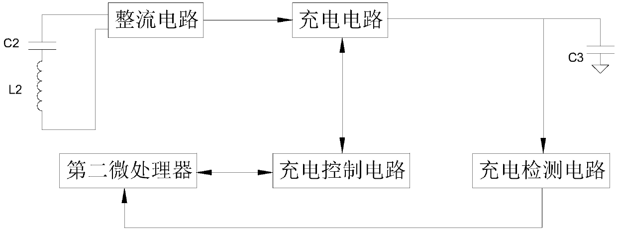
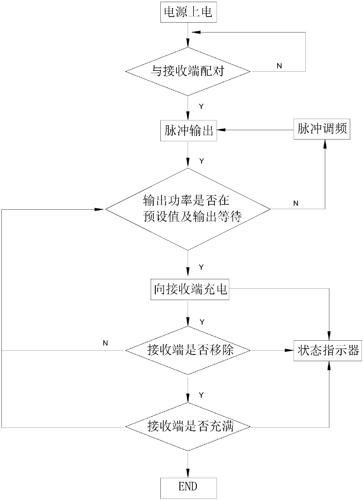
[0045] Depend on Figure 1 to Figure 9 It can be seen that the electromagnetic resonance intelligent wireless charging system described in this embodiment includes a transmitting end and at least one receiving end;

[0046] The transmitter includes a first microprocessor, a first resonant network for converting alternating current into electromagnetic energy, a pulse output circuit 2 for providing alternating current to the first resonant network, and a driver for driving the pulse output circuit 2 to work. Circuit 1; the first microprocessor controls the magnitude of the alternating current output by the pulse output circuit 2 through the drive circuit 1; the transmitting end also includes a feedback circuit; the feedback circuit includes a circuit for detecting the output power of the first resonant network and feeding back To the first feedback end of the first microprocessor an...


PUM


Abstract

The present invention relates to the field of wireless charging technologies, and in particular, to an electromagnetic resonance intelligent wireless charge system and method for use with charge. Thesystem comprises a transmitting end and at least one receiving end, the transmitting end comprises a first microprocessor, a 2.4G a wireless transceiver circuit, a first resonant network, a pulse output circuit and a drive circuit, and the transmitting end further comprises a feedback circuit and a DC power circuit; each receiving end comprises an energy storage body, a second microprocessor, a second resonant network, a rectification circuit, a charge circuit and a charge control circuit; and each receiving end further comprises a charge detection circuit. Through the arrangement mentioned above, the charged wireless device can be moved with being charged in a certain area range so as to achieve a permanent power-off function. The charged wireless device is internally provided with an energy storage super capacitor to achieve that the charged wireless device can be continuously used for a certain time after is divorced from a charge device and to perform transmission of related statesignals and state indication.

Description

technical field [0001] The invention relates to the technical field of wireless charging, in particular to an electromagnetic resonance intelligent wireless charging system and charging method while charging. Background technique [0002] With the development and progress of technology, more and more wireless mice and other wireless devices need to be charged. Whenever they are in use, they need to pay attention to the power status. Every time they charge, they need to find a charging cable and plug in the charging cable to charge the device, and Affects the use of the device during charging or causes inconvenient use. [0003] In order to further improve the user experience and solve the problem that some current mouse kits with charging while moving can not effectively manage the various states of the energy storage components on the mouse side during the charging process and the status indication of leaving the charging area, it is necessary to study a set of New wireles...

Claims


Application Information

Patent Timeline
IPC IPC(8): H02J7/00H02J50/12H02J50/40
CPCH02J7/025H02J50/12H02J50/40
Inventor 李晨曦黄建锋
Owner DONGGUAN TOGRAN ELECTRONICS TECH
Features
  • R&D
  • Intellectual Property
  • Life Sciences
  • Materials
  • Tech Scout
  • Unparalleled Data Quality
  • Higher Quality Content
  • 60% Fewer Hallucinations
Learn More